Laser apparatus and extreme ultraviolet light source apparatus

Active Publication Date: 2010-08-05
GIGAPHOTON
View PDF20 Cites 79 Cited by
  • Summary
  • Abstract
  • Description
  • Claims
  • Application Information

AI Technical Summary

Benefits of technology

[0013]It is therefore an object of the present invention to resolve the above-described problems and to provide a laser apparatus and an extreme ultraviolet light source apparatus which make possible to not only achieve easy handling of th

Problems solved by technology

However, it is a problem that the use of the CO2 gas laser being a high power molecular laser as an MO for the same type of the CO2 gas laser will make the structure of a controller such as a pulse controller complicated, and moreover, will make handling of the

Method used


Image

  • Laser apparatus and extreme ultraviolet light source apparatus
  • Laser apparatus and extreme ultraviolet light source apparatus
  • Laser apparatus and extreme ultraviolet light source apparatus

Examples


first embodiment

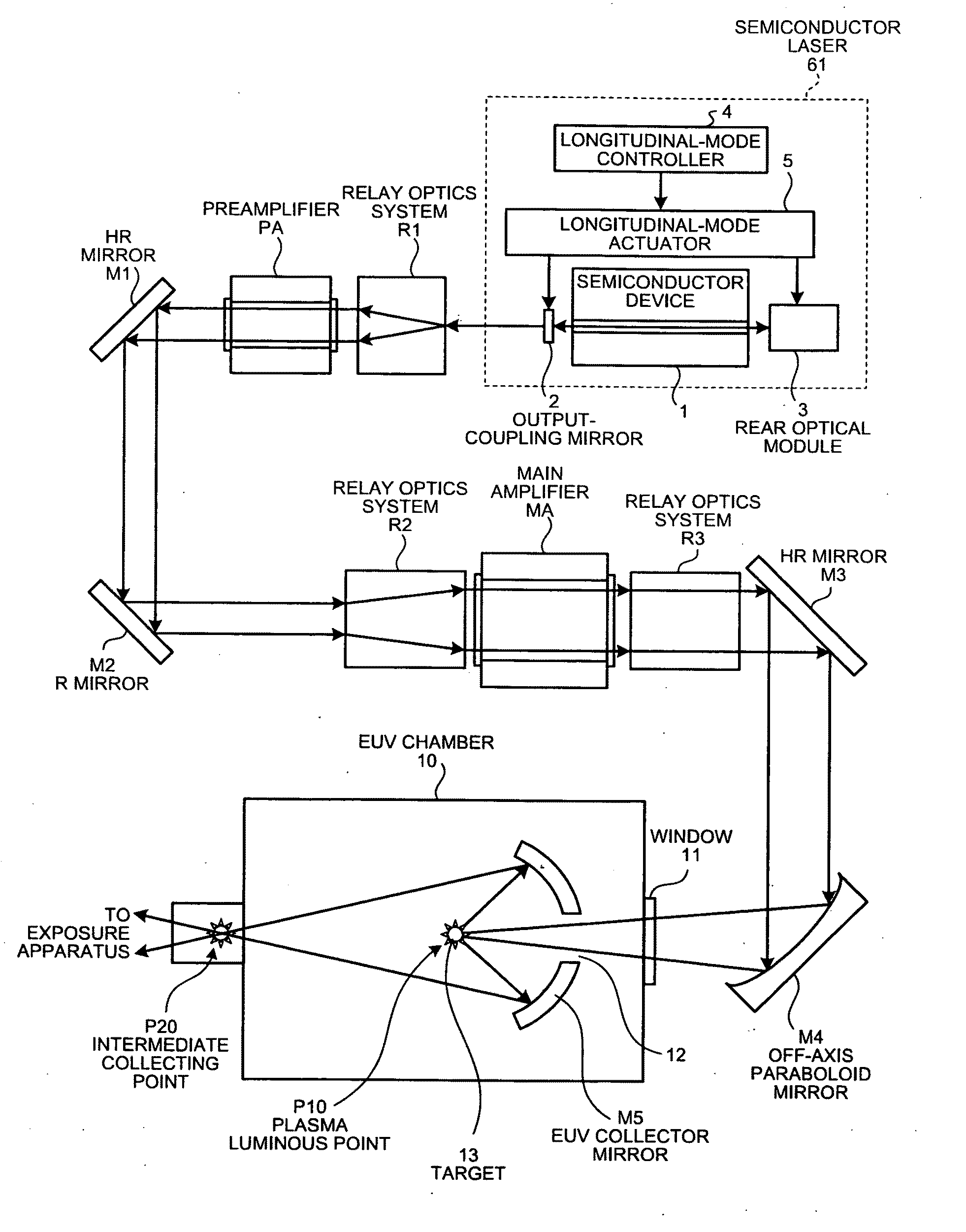
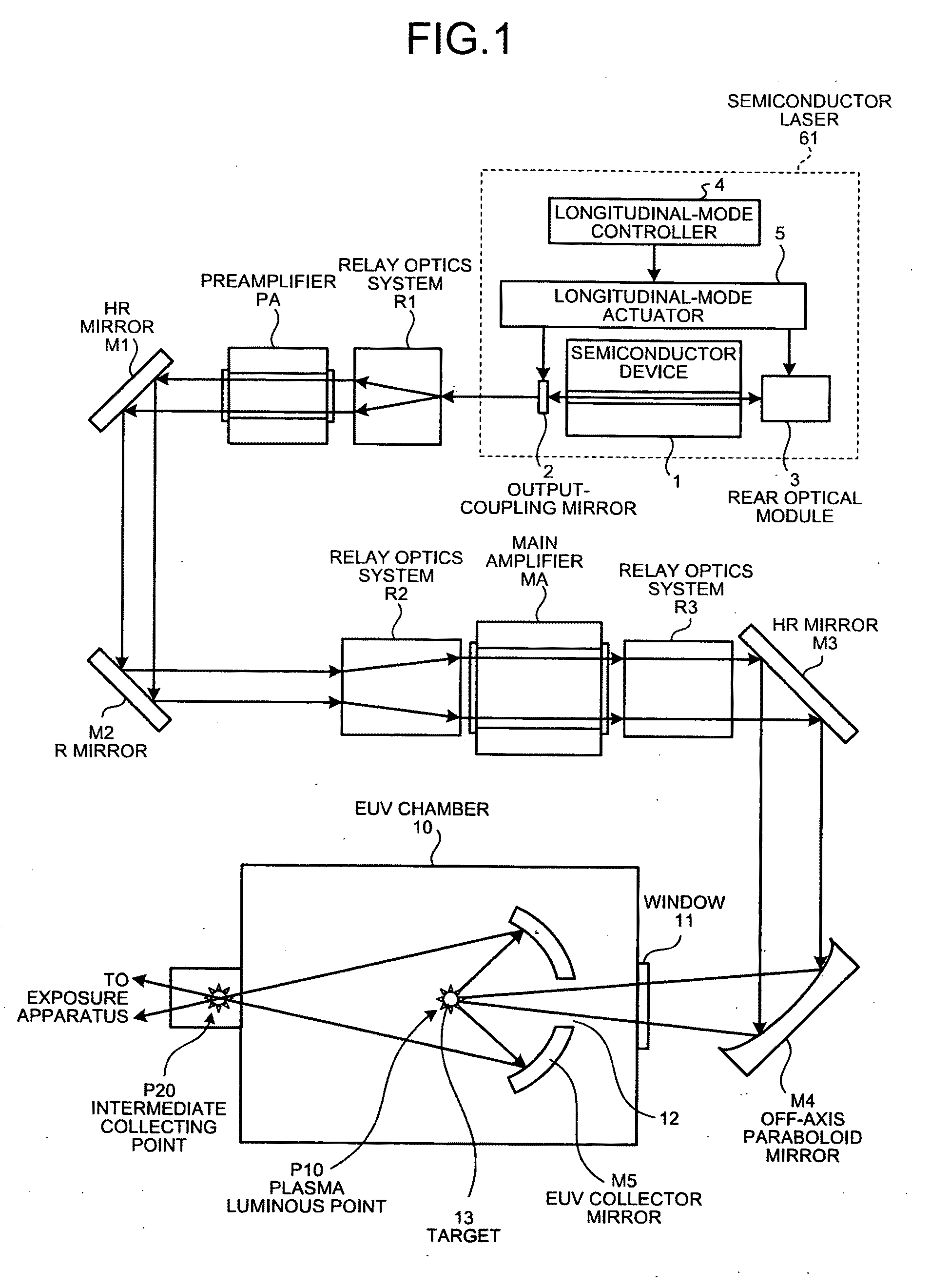
[0048]FIG. 1 is a schematic diagram showing a structure of an extreme ultraviolet light source (EUV) apparatus having a laser apparatus according to a first embodiment of the present invention. This EUV apparatus comprises, as main components, a driver laser which outputs laser lights (so-called seed laser lights) for exciting target materials which are generation sources of EUV light, and an EUV generator which generates the EUV light using the laser lights from the driver laser. The driver laser includes a semiconductor-laser 61 which is a master oscillator, and a multi-stage amplifier which is a double-stage amplifier constituted from a preamplifier PA and a main amplifier MA. Both of the preamplifier PA and the main amplifier MA have mixed gases including CO2 gas as as an amplifying agency.

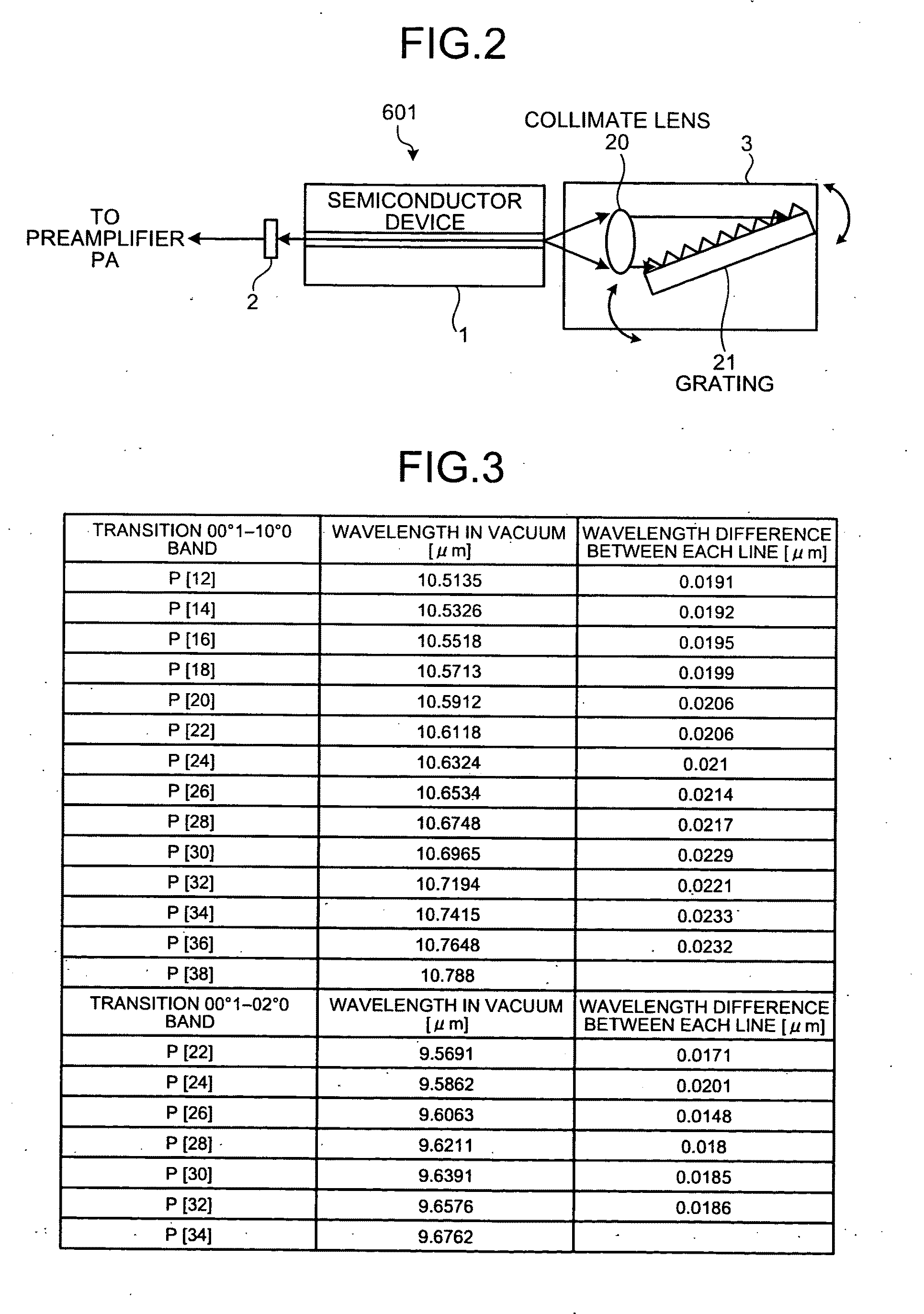
[0049]The semiconductor laser 61 has a semiconductor device 1, an output-coupling mirror 2, a rear optical-module 3, a longitudinal-mode actuator 5, and a longitudinal-mode controller 4. The s...

second embodiment

[0060]Next, a second embodiment of the present invention will be described in detail. In the above-mentioned first embodiment, the single-longitudinal-mode pulse laser light L1 is used as a laser light for being amplified by the resonator 601 including the semiconductor device 1, and the wavelength of this single-longitudinal-mode pulse laser light L1 is adjusted to one of the amplifiable lines S1 to S7 of the preamplifier PA and the main amplifier MA. On the other hand, in the second embodiment, multiple-longitudinal-mode pulse laser lights are used as laser lights for being amplified by a resonator including a semiconductor device, and wavelengths of the multiple-longitudinal-mode pulse laser lights are adjusted to amplifiable lines of the preamplifier PA and the main amplifier MA, respectively. In the following, the same reference numbers will be used for the structural elements that are the same as the first embodiment, and redundant explanations of those structural elements wil...

third embodiment

[0065]Next, a third embodiment of the present invention will be described in detail. In the third embodiment, as shown in FIG. 7, by adjusting the wavelengths of the multiple-longitudinal-mode pulse laser lights L21 to L27 to all of the amplifiable lines S1 to S7 of the preamplifier PA and the main amplifier MA, the multiple-longitudinal-mode pulse laser lights L21 to L27 are amplified, respectively. In the following, the same reference numbers will be used for the structural elements that are the same as the first embodiment, and redundant explanations of those structural elements will be omitted.

[0066]In this case, as with the case of the second embodiment, a light path length ‘nd’ of the resonator 601A is adjusted so that the longitudinal-mode intervals FSR are made to substantively correspond with the wavelength intervals among the amplifiable lines S1 to S7. For example, when the light path length ‘nd’ is nd=0.0028 nm=2.8 mm, each of the longitudinal-mode interval FSR is FSR=0....


PUM


Abstract

An extreme ultraviolet light source apparatus comprises a laser apparatus having a master oscillator outputting one or more longitudinal-mode-laser lights, an amplifier with a molecular gas as an amplifying agency amplifying a longitudinal-mode laser light of which wavelength is included in one of amplifiable lines, and a controller adjusting the master oscillator so that the wavelength of the longitudinal-mode laser light outputted from the master oscillator is included in one of the amplifiable lines, the laser apparatus being used as a driver laser, wherein the laser apparatus irradiates a target material with a laser light for generating plasma, and the extreme ultraviolet light is emitted from the plasma and outputted from the extreme ultraviolet light source apparatus.

Description

CROSS-REFERENCE TO RELATED APPLICATIONS[0001]This application is based upon and claims the benefit of priority from the prior Japanese Patent Applications No. 2008-267519, filed on Oct. 16, 2008, No. 2008-334007, filed on Dec. 26, 2008, and No. 2009-211072, filed on Sep. 11, 2009; the entire contents of which are incorporated herein by reference.BACKGROUND OF THE INVENTION[0002]1. Field of the Invention[0003]The present invention relates to a laser apparatus as being a driver laser for an extreme ultraviolet light source apparatus used for an exposure apparatus and an extreme ultraviolet light source apparatus using such laser apparatus.[0004]2. Description of the Related Art[0005]In recent years, along with a progress in a miniaturization of semiconductor device, miniaturization of transcription pattern used in photolithography in semiconductor process has developed rapidly. In the next generation, microfabrication to the extent of 70 nm to 45 nm, or even to the extent of 32 nm and...

Claims


Application Information

Patent Timeline
IPC IPC(8): H05G2/00H01S3/10H01S3/22H01S3/0941
CPCB82Y20/00G03F7/70033H01S3/107H01S3/2232H01S3/2316H01S3/235H01S5/02284H01S5/0654H01S5/06837H01S5/0687H01S5/141H01S5/3402H01S5/4012H01S5/4062H01S5/4087H01S3/0007H01S5/02251
Inventor WAKABAYASHI, OSAMUENDO, AKIRANOWAK, KRZYSZTOFSUGANUMA, TAKASHIMORIYA, MASATO
Owner GIGAPHOTON
Why Eureka
Try Eureka