
Filters for selective removal of large particles from particle slurries

Inactive Publication Date: 2010-08-12
EI DU PONT DE NEMOURS & CO
View PDF45 Cites 1 Cited by
  • Summary
  • Abstract
  • Description
  • Claims
  • Application Information

AI Technical Summary

Benefits of technology

[0018]In a still further embodiment said fabric of step (i) has been calendered effective to reduce the pore size of said fabric by about 20-50% less than a first pore size before calendering of said fabric.

Problems solved by technology

In this regard, a relatively rough surface topography may result in poor coverage by subsequently deposited layers, and in the formation of voids between layers.
As circuit densities in semiconductor dies continue to increase, any such defects become unacceptable and may render the circuit either inoperable or lower its performance to less than optimal.
Although the metal-type slurries generally are more susceptible to agglomeration than the oxide types, the problem may present in either type of slurry depending upon the slurry composition and ambient conditions.
Should the agglomerated particles be entrained within the CMP slurry, significant damage to the wafer surface being planarized can result.
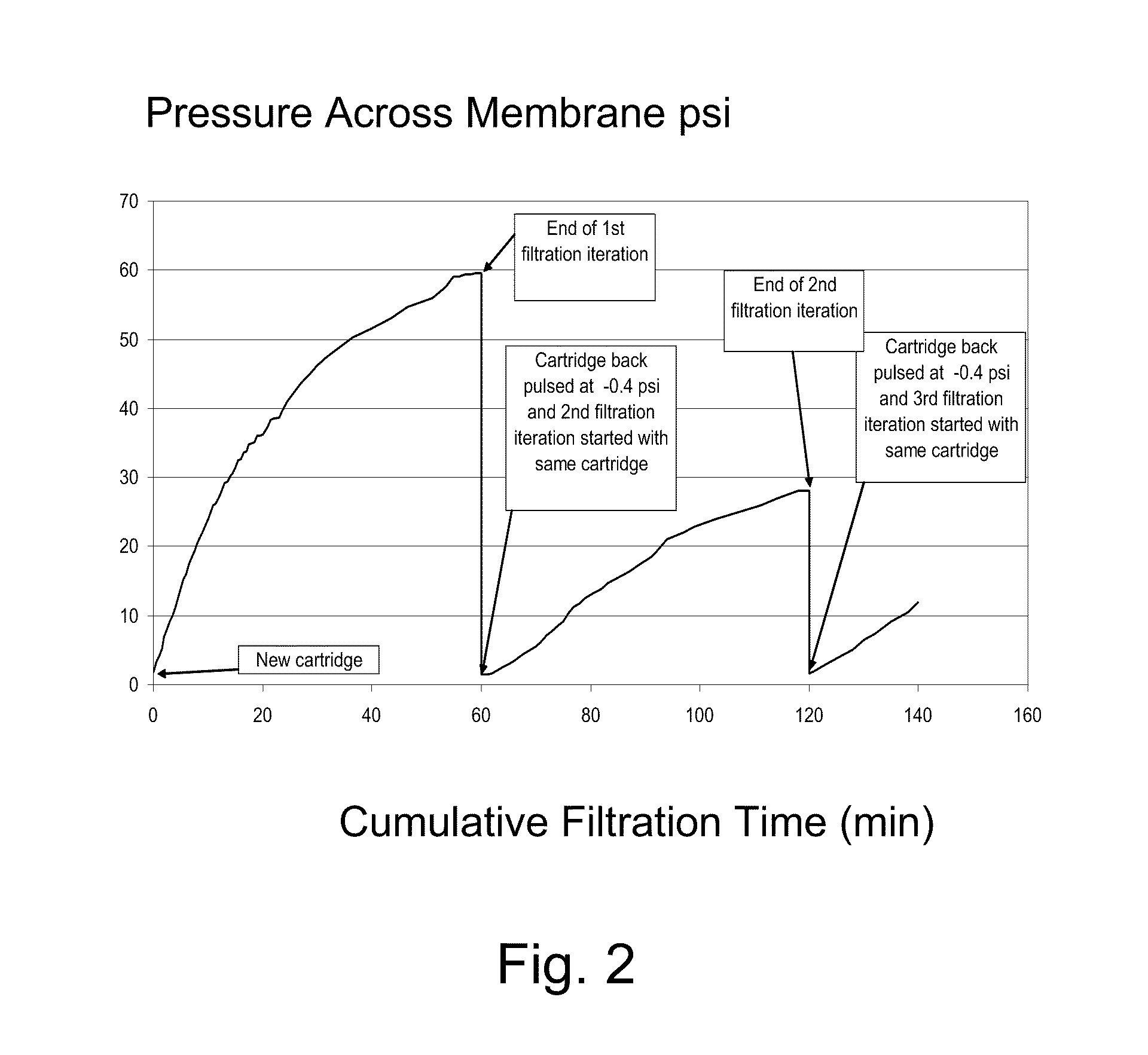
In service, however, membranes filters of such type were observed to load almost instantaneously with particulate and soon were judged unacceptable for the CMP process.
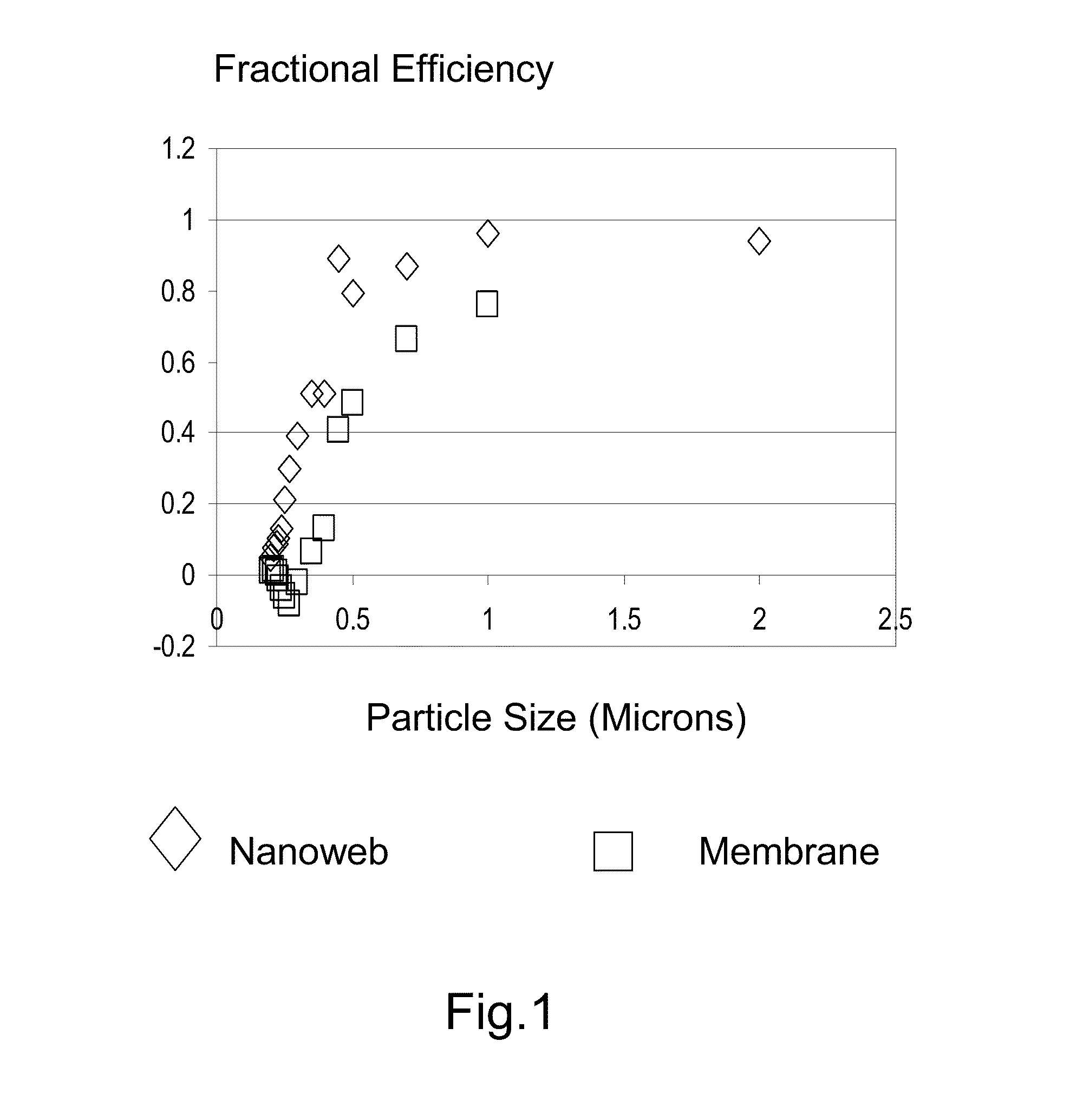
As a drawback, the more open and permeable structure does allow for some passage of large size particles which could damage the substrate being planarized.

Method used


Image

  • Filters for selective removal of large particles from particle slurries
  • Filters for selective removal of large particles from particle slurries

Examples


examples

[0045]A 24% solution of polyamide-6,6 in formic acid was spun by electroblowing as described in WO 03 / 080905. The number average fiber diameter for Example 1 was about 420 nm. The as-spun media in Example 1 was co-pleated between two scrims of spunbond media for support. The pleated media was converted to a standard 222 10″ cartridge with approximately seven square feet of surface area of the media.

[0046]The media for Example 2 was calendered from Example 1. The nanofiber sheets of Examples 1 were calendered by delivering the nanofiber sheets to a two roll calender nip from an unwind. A device for spreading the sheet prior to the nip was used to maintain a flat, wrinkle free sheet upon entering the nip. The hard roll was a 16.04 inch (40.74 cm) diameter steel roll, and the soft roll was a cotton-wool composite roll having a Shore D hardness of about 78, and about 20.67 inches (52.50 cm) in diameter. The media were calendered with the steel roll heated to 150° C. and at line speed of...


PUM

PropertyMeasurementUnit
Lengthaaaaaaaaaa
Lengthaaaaaaaaaa
Lengthaaaaaaaaaa

Abstract

A method for removing the high particle size tail of the particle size distribution of a slurry while leaving desirable smaller particles in the slurry. The method involves providing a filter media having a first and second side and being formed of at least one sheet of a fabric that has at least one layer comprising polymeric fibers having a mean number average fiber diameter of less than 1000 nm. A slurry stream is then supplied to one face of the fabric. The stream has a multiplicity of particle sizes comprising a first set of particles of maximum dimension less than 0.1 microns and a second set of particles of maximum individual dimension of greater than 0.45 microns to the first side of said filter media. The slurry stream is passed through said filter media to the second side thereof whereby at least a portion of the larger particles in the slurry are retained on the first side of said media. The filtration efficiency of the fabric towards the first set of particles is less than 0.05 and the filtration efficiency towards the second set of particles is greater than 0.8.

Description

FIELD OF THE INVENTION[0001]The present invention relates broadly to filters for separation of the large size fraction of particles from slurries comprising large and small particles, and in particular to chemical-mechanical polishing (CMP) slurries.BACKGROUND[0002]In the general mass production of semiconductor devices, hundreds of identical “integrated” circuit traces are photolithographically imaged over several layers on a single semiconducting wafer which, in turn, is cut into hundreds of identical dies or chips. Within each of the die layers, the circuit traces are insulated from the next layer by an insulating material. It is desirable that the insulating layers are provided as having a smooth surface topography. In this regard, a relatively rough surface topography may result in poor coverage by subsequently deposited layers, and in the formation of voids between layers. As circuit densities in semiconductor dies continue to increase, any such defects become unacceptable and...

Claims


Application Information

Patent Timeline
IPC IPC(8): B01D37/00B01D29/46
CPCB01D2239/025B01D39/1623B01D2259/126
Inventor VELU, YOGESHWAR K.COMPTON, TIMOTHY FREDERICK
Owner EI DU PONT DE NEMOURS & CO
Learn More