Welding control apparatus for pulse arc welding of consumed electrode type, arc length control method for use with the same, and welding system including the welding control apparatus

a control apparatus and consumed electrode technology, applied in the direction of arc welding apparatus, welding apparatus, manufacturing tools, etc., can solve the problem of affecting the welding effect of the welding control apparatus, the above-described precondition cannot be applied to the technique, and the balance between the feed speed and the melting rate is lost, etc. problem, to achieve the effect of satisfying the precondition, reducing spatters, and high correlation

Active Publication Date: 2010-08-12
KOBE STEEL LTD
View PDF4 Cites 28 Cited by
  • Summary
  • Abstract
  • Description
  • Claims
  • Application Information

AI Technical Summary

Benefits of technology

[0021]Accordingly, an object of the present invention is to solve the above-mentioned problems and to provide an arc length control technique adapted for pulse arc welding of consumed electrode type using, as shield gas, carbon dioxide (gas) or a gas mixture containing carbon dioxide as a main component, which can precisely suppress a variation in arc length caused by disturbances.
[0022]Another object of the present invention is to provide an arc length control technique which can suppress generation of spatters without impairing regularity of the droplet transfer even when the tip-to-base material distance is momentarily changed with weaving of the tip within a gap (grove).

Problems solved by technology

More specifically, if the wire feed speed varies during the welding due to, e.g., feed resistance caused in a wire feed path, the balance between the wire feed speed and the melting rate is lost, thus causing a variation in the arc length.
However, the above-described precondition cannot be applied to the technique disclosed in Japanese Unexamined Patent Application Publication No. 2007-237270.
This results in the problem of causing a variation in droplet size and impairing regularity of the droplet transfer.
Also, if the base period Tb is too long, the droplet contacts a molten metal pool, thus generating spatters by a short-circuiting.

Method used


Image

  • Welding control apparatus for pulse arc welding of consumed electrode type, arc length control method for use with the same, and welding system including the welding control apparatus
  • Welding control apparatus for pulse arc welding of consumed electrode type, arc length control method for use with the same, and welding system including the welding control apparatus
  • Welding control apparatus for pulse arc welding of consumed electrode type, arc length control method for use with the same, and welding system including the welding control apparatus

Examples


first embodiment

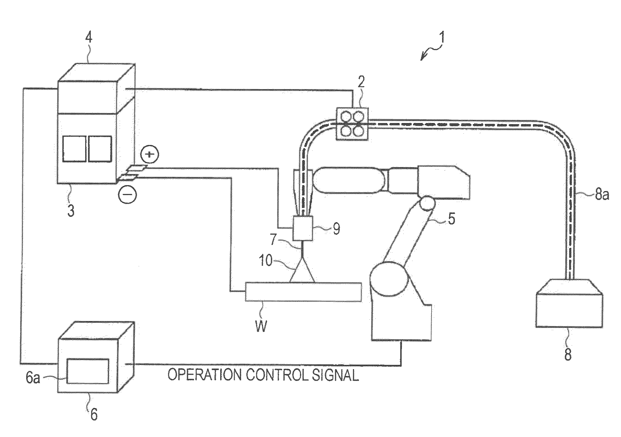
[0082]FIG. 9 is a block diagram illustrating the configuration of the welding control apparatus according to the present invention. FIG. 9 illustrates the welding control apparatus 4 and the welding power supply 3 for feeding the wire 7 to the torch 9 in accordance with a signal output from the welding control apparatus 4.

[0083]An output control device 21 is connected to a commercial power supply of 3-phase 200 V, for example, and a current applied to the output control device 21 passes through a transformer, a rectifier (diode), and a DC reactor, which are all not shown in the drawing, for application to a contact tip 23 through a current detector 22 for detecting the welding current. The contact tip 23 is contained in the torch 9 indicated by a dotted line.

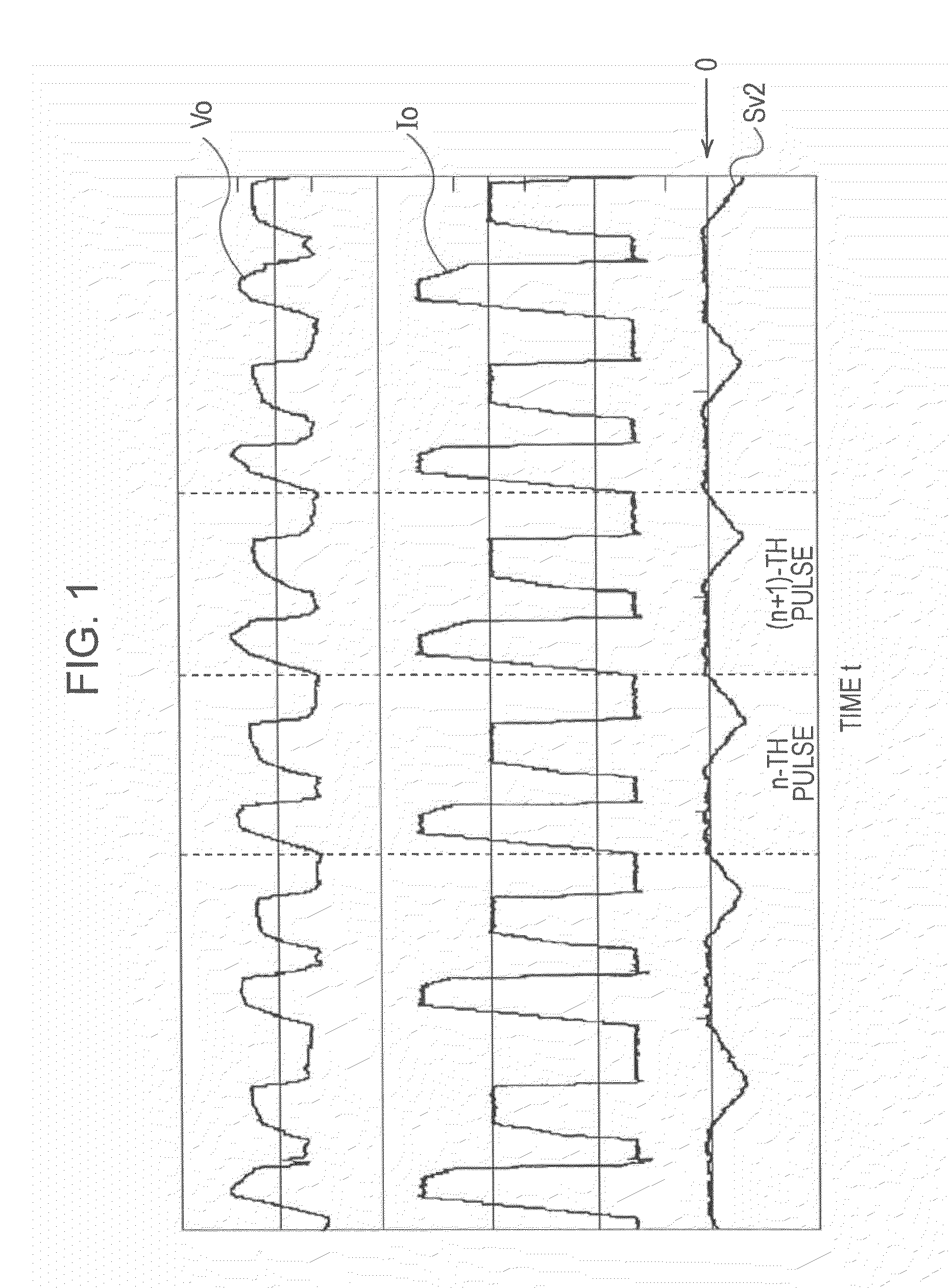
[0084]The current detector 22 detects the instantaneous value Io of the welding current and outputs a detected current signal to an output controller 25. Further, the current detector 22 detects the instantaneous value Io2 of th...

second embodiment

Modification of Second Embodiment

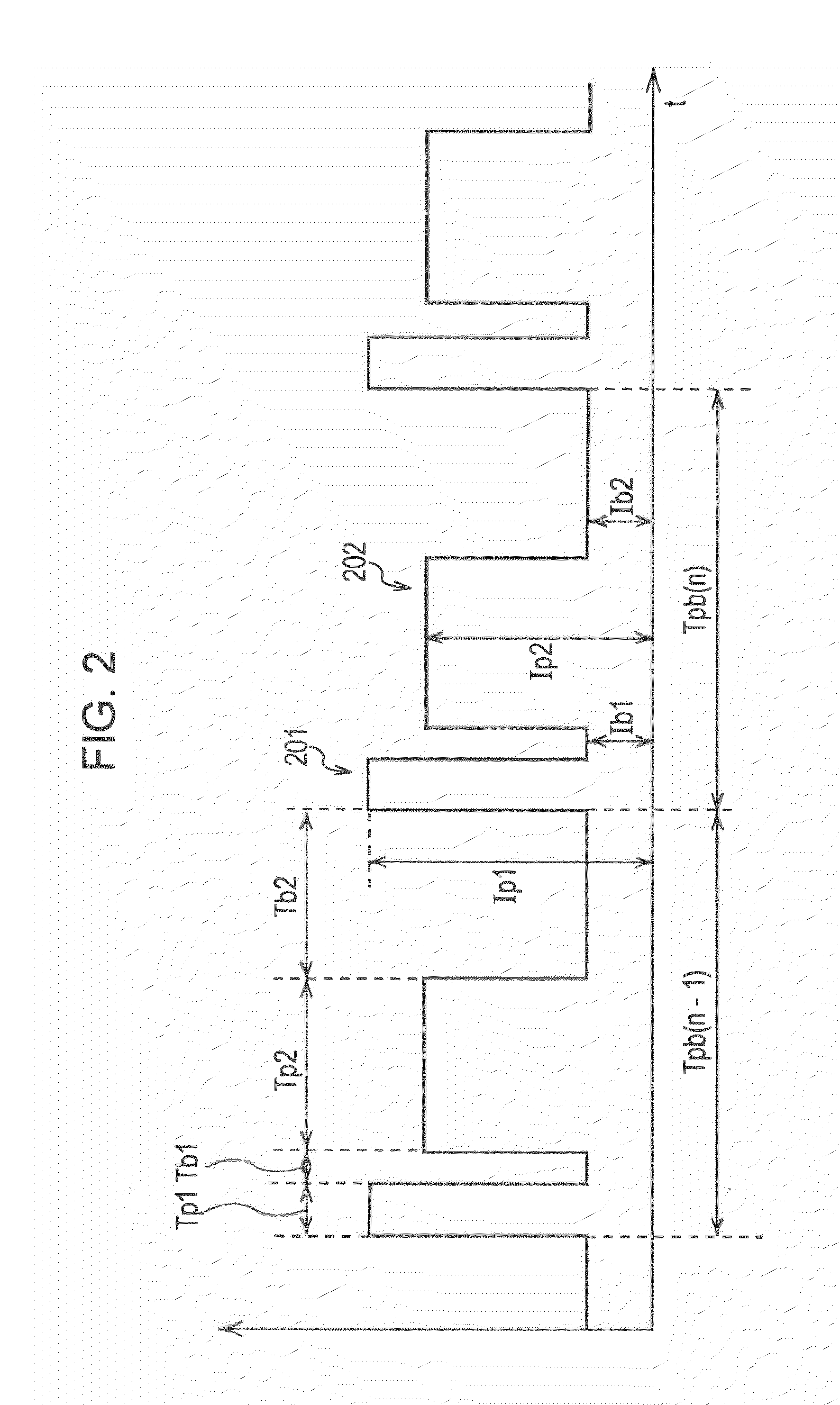
[0111]In a modification of the second embodiment, an upper limit value and a lower limit value are previously set for the addition / reduction value ΔTp2(n) that is calculated by the waveform generator 31 based on the above-mentioned formula (2). More specifically, the waveform setting unit 32 additionally sets a maximum value of an increase range and a maximum value of a decrease range for the addition / reduction value ΔTp2(n) in the waveform generator 31. The maximum value of the increase range and the maximum value of the decrease range for the addition / reduction value ΔTp2(n) are set in advance so that the value of the peak period of the second pulse period is held at a proper value. The proper value of the peak period of the second pulse period can be set by previously obtaining such a range of the peak period value as not disturbing the regularity of the droplet transfer with experiments, for example, and by selecting a value within the obtained r...

third embodiment

Modification of Third Embodiment

[0120]In a modification of the third embodiment, an upper limit value and a lower limit value are previously set for the addition / reduction value ΔIp2(n) that is calculated by the waveform generator 31 based on the above-mentioned formula (3). More specifically, the waveform setting unit 32 additionally sets a maximum value of an increase range and a maximum value of a decrease range for the addition / reduction value ΔIp2(n) in the waveform generator 31. The maximum value of the increase range and the maximum value of the decrease range for the addition / reduction value ΔIp2(n) are set in advance so that the value of the peak current in the second pulse period is held at a proper value. The proper value of the peak current in the second pulse period can be set by previously obtaining such a range of the peak current value as not disturbing the regularity of the droplet transfer with experiments, for example, and by selecting a value within the obtained ...


PUM

PropertyMeasurementUnit
welding currentaaaaaaaaaa
welding voltageaaaaaaaaaa
currentaaaaaaaaaa

Abstract

A welding control apparatus according to the present invention includes an integrator for starting calculation of a voltage error integral value Sv2, expressed by a formula (1) given below, from a time when a first pulse period ends and a second pulse period starts in a pulse cycle, based on various data of information regarding a gradient Ks of an external characteristic of a welding power supply and a welding current setting value Is2 and a welding voltage setting value Vs2 both in a second pulse period, which are preset as parameters in the formula (1), as well as on an instantaneous value Io2 of a welding current and an instantaneous value Vo2 of a welding voltage both detected in the second pulse period, a comparator for comparatively determining whether a value of the voltage error integral value Sv2 provided as the calculation result has become 0, and a waveform generator for, per pulse cycle, terminating the relevant pulse cycle and starting a next pulse cycle at a time when the value of the voltage error integral value Sv2 has become 0, whereby a variation in an arc length caused by disturbances is precisely suppressed in pulse arc welding of consumed electrode type:Sv2=∫{Ks(Io2−Is2)+Vs2−Vo2}dt  (1)

Description

BACKGROUND OF THE INVENTION[0001]1. Field of the Invention[0002]The present invention relates to an arc length control technique adapted for pulse arc welding of consumed electrode type using, as shield gas, carbon dioxide (gas) or a gas mixture containing carbon dioxide as a main component.[0003]2. Description of the Related Art[0004]From the necessity of properly keeping an arc length to maintain satisfactory welding quality, there is known an arc length control technique for suppressing changes of the arc length during the welding (see Japanese Unexamined Patent Application Publication No. 2002-361417 and Japanese Patent No. 3147046). Qualitatively, the arc length is determined based on balance between a feed speed of a welding wire (i.e., a wire feed speed) and a melting rate of the wire. More specifically, if the wire feed speed varies during the welding due to, e.g., feed resistance caused in a wire feed path, the balance between the wire feed speed and the melting rate is los...

Claims


Application Information

Patent Timeline
Patent Type & Authority Applications(United States)
IPC IPC(8): B23K9/10
CPCB23K9/073B23K9/092B23K9/173B23K9/0956B23K9/0953
Inventor YAMAZAKI, KEISUZUKI, KEIICHIHONMA, MASAHIROSATO, EIJI
Owner KOBE STEEL LTD
Why Eureka
Try Eureka