Self Powered Sensor with Radioisotope source

a self-powered sensor and radioisotope technology, applied in the direction of instruments, measurement with semiconductor devices, nuclear engineering, etc., can solve the problems of long operating lifetime, high cost of battery monitoring and replacement, and complex signal processing for conversion of optical signals into electrical signals, so as to increase the lifetime of battery powered sensor suites and save battery power

Active Publication Date: 2010-08-26
CORNELL RES FOUND - CORNELL CENT FOR TECH ENTERPRISE & COMMLIZATION CCTEC
View PDF15 Cites 7 Cited by
  • Summary
  • Abstract
  • Description
  • Claims
  • Application Information

AI Technical Summary

Benefits of technology

[0010]The present invention addresses the foregoing needs with a method and apparatus for increasing the lifetime of battery powered sensor suites that employs zero-power sensors which can be passive or self-powered. Self-powered sensors can wake-up the rest of the sensor system when required, conserving the battery power for emergency computations and communications.
[0015]The sensor topology of the present invention is readily adapted to sensing other physical phenomena including shock and chemical concentrations. The sensors of exemplary embodiments of the present invention consume zero-battery-power and can potentially extend the lifetime of condition monitoring sensor suites to multiple decades. These zero-battery-power sensors allow event-based power management of unattended sensor systems and orders of magnitude reduction in average power consumption.
[0016]Preferably, the sensors employ Nickel-63, a safe radioisotope for which power output is nearly independent of the ambient conditions, and Nickel-63 can have several decades of useful life, since the half-life is 100.2 years. For example, a 2-milliCurie Nickel-63 thin-film emits low energy (average energy=17 keV) β-particles with penetration depths<10 μm in solids. As a result, Nickel-63 can be deployed safely without substantial shielding or concerns about security.
[0017]A MEMS cantilever structure-based fissile material proximity sensor embodiment provides an improved means for the detection and prevention of the clandestine transport of fissile materials (including 235U and 239Pu), substances used for producing weapons of mass destruction. The sensor detects both the neutrons and the relatively high intensity of γ rays (E.g.>3:0 MeV) that are emitted from short-lived fission fragments
[0019]The use of micro-mechanical switches results in a complete “1” or “0” switching, can be used to “wake-up” the sensor electronics, which might be “asleep” until something is detected, and hence conserve battery power. The detector is optionally configured to consume zero power when in “detect” mode, allowing long term monitoring in hostile environments where battery replacement is not feasible, and the power required to bias the cantilevers are provided by a radioactive thin film. The beta particles generate Bremsstrahlung, whose energy is low enough (<80 keV) that will not interfere with the higher energy X-rays to be detected due to external fission.

Problems solved by technology

Wireless sensor suites deployed in remote and inaccessible areas need long operating lifetimes as battery monitoring and replacement is often cost-prohibitive.
Self-powered sensors based on passive fiber-optics have been demonstrated, but fiber-optic based approaches require complicated signal processing for conversion of optical signals to electrical signals.
The active detectors are very sensitive but may consume significant power for operation and are thus unsafe for portable applications due to the interrogating irradiation.
In contrast, passive detectors are low power consuming and small in size, but their sensitivity is often limited.

Method used


Image

  • Self Powered Sensor with Radioisotope source
  • Self Powered Sensor with Radioisotope source
  • Self Powered Sensor with Radioisotope source

Examples


Embodiment Construction

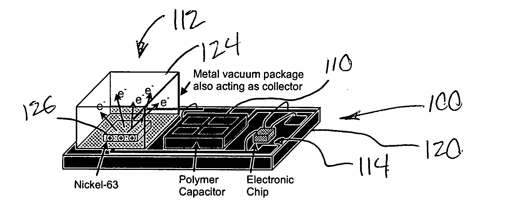
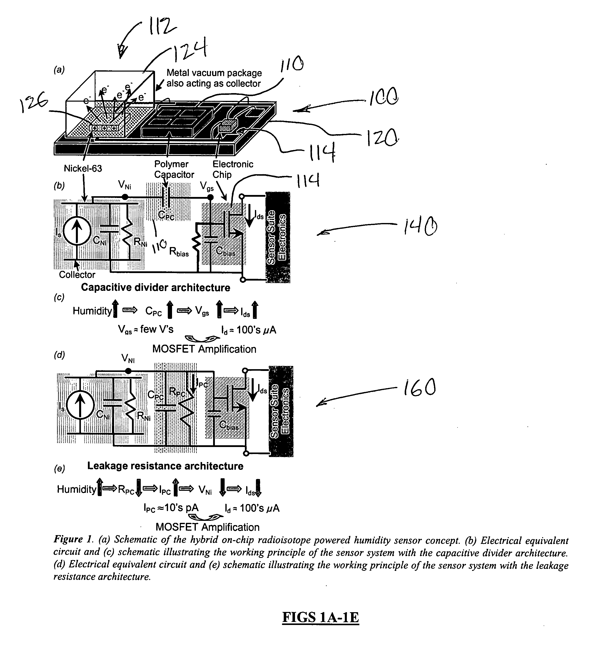
[0052]As shown in FIGS. 1a-1e, hybrid on-chip radioisotope powered humidity sensor 100 comprises a polymer capacitor CPC 110, a radioisotope source 112 and a transistor, preferably a MOSFET 114. Sensor 100 in prototypes has been configured on a substrate or printed circuit board 120 which supports a conductive metal package or box-shaped shield 124 that functions as a collector for charge emitted from a radioisotope emitter such as the Nickel-63 thin film segment 126. Radioisotope source 112 effectively provides a current source IS, shunted by an intrinsic capacitance CNi and resistance RNi, across which are developed a radioisotope source voltage VNi, as shown in FIG. 1b.

[0053]Radioisotope source 112 generates voltage biases employed to power polymer capacitor CPC 110 for the self-powered sensor 100. Self-powered humidity sensor 100 can significantly extend the operating lifetime of battery powered wireless sensor suites. There are two capacitor biasing architectures. Leakage resi...


PUM


Abstract

A self-powered sensor (e.g., 100, 180, 220, 400) can wake-up systems requiring a trigger signal to wake-up circuits or systems in power-sleep mode, conserving the battery power for emergency computations and communications. In a humidity sensor embodiment 100, radioisotope generated voltage biases are employed to power sensor capacitors to realize self-powered sensors. A first self-powered capacitor biasing architecture 160 is based on changes in the leakage resistance of the polymer capacitor 110, and a second self-powered capacitor biasing architecture 140 uses changes in the capacitance of the polymer capacitor. Another sensor embodiment uses changes in the capacitance or leakage resistance of the sensor capacitor to modulate conductance of a MOSFET 114, realizing an easily readable electronic output signal. A temperature sensor embodiment 180 and a MEMS cantilever structure based fissile material proximity sensor embodiment 400 are also disclosed.

Description

CROSS REFERENCE TO RELATED APPLICATIONS[0001]This application claims the benefit of priority under 35 U.S.C. 119(e) of: (a) U.S. Application No. 60 / 845,423 filed on Sep. 18, 2006 and (b) U.S. Application No. 60 / 942,842 filed on Jun. 1, 2007, the entire disclosures of which are incorporated herein by reference.BACKGROUND OF THE INVENTION[0002]1. Field of the Invention[0003]The present invention relates in general to self powered sensors and methods for providing power to circuits and sensors embedded in systems adapted for use in hostile or remote environments.[0004]2. Description of the Background Art[0005]Wireless sensor suites deployed in remote and inaccessible areas need long operating lifetimes as battery monitoring and replacement is often cost-prohibitive. Such applications include long-term health monitoring of tactical missiles, industrial equipment, buildings, etc. In addition to efforts on increasing the lifetime of the conventional electrochemical batteries currently in ...

Claims


Application Information

Patent Timeline
Patent Type & Authority Applications(United States)
IPC IPC(8): G01T3/08H01L31/102G01T1/24G01R27/26
CPCG01T1/2018G21H5/00G01T7/00G01T3/06
Inventor LAL, AMITDUGGIRALA, RAJESHCHANDRASEKHAR, MVS
Owner CORNELL RES FOUND - CORNELL CENT FOR TECH ENTERPRISE & COMMLIZATION CCTEC
Why Eureka
Try Eureka