

Spectrum spread clock generation device
a technology of clock signal and spread spectrum, which is applied in the direction of oscillation generator, pulse automatic control, resonance circuit tuning, etc., can solve problems such as electromagnetic interference (emi), and achieve the effect of improving the jitter and noise properties of spread-spectrum processed clock signal
- Summary
- Abstract
- Description
- Claims
- Application Information
AI Technical Summary
Benefits of technology
Problems solved by technology
Method used
Image

Examples
first embodiment
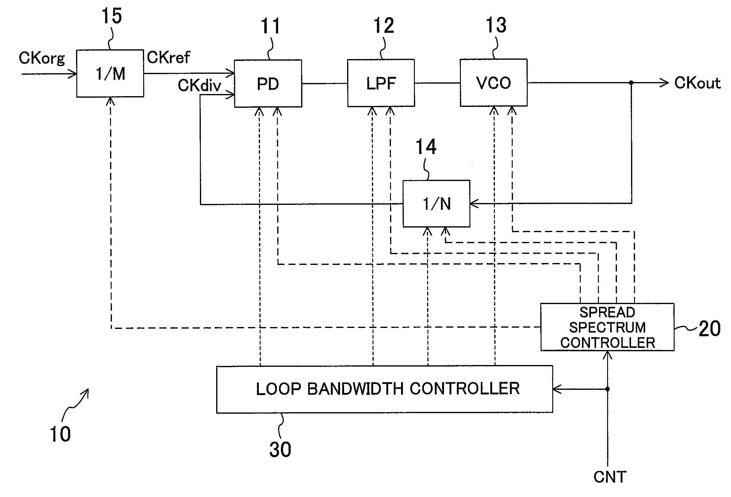
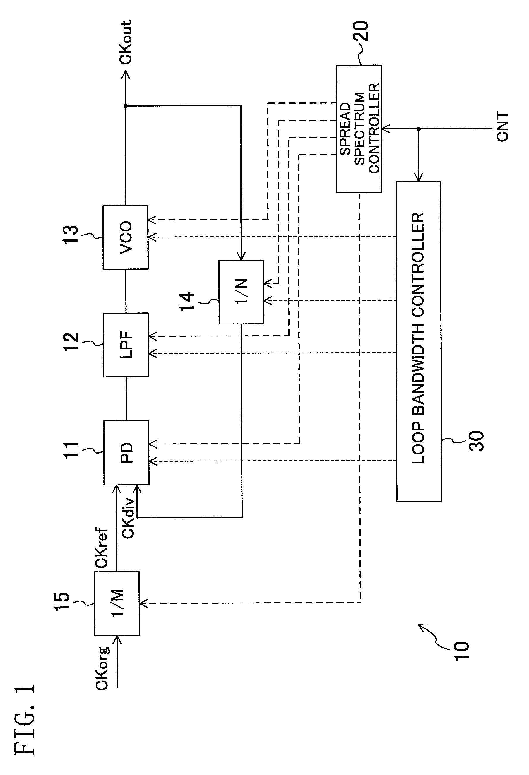
[0062]FIG. 1 illustrates a configuration of a spread-spectrum clock generator according to a first embodiment. A PLL 10 receives a clock signal CKref (a reference clock signal), and outputs a clock signal CKout. Specifically, a frequency divider 14 divides a frequency of the clock signal CKout. A phase detector (PD) 11 compares phases of a clock signal CKdiv output from the frequency divider 14, and the clock signal CKref. A loop filter (LPF) 13 smooths an output from the PD 11. A voltage-controlled oscillator (VCO) 13 oscillates at a frequency according to an input voltage, and outputs the clock signal CKout. A frequency divider 15 divides a frequency of a clock signal CKorg (an original clock signal) to generate the clock signal CKref.
[0063]A spread spectrum controller 20 controls the PLL 10 so that it outputs a spread-spectrum processed clock signal. Specifically, the spread spectrum controller 20 modulates the input voltage to the VCO 13, changes a dividing ratio of the frequenc...
example configuration 1
of Voltage-controlled Oscillator
[0074]FIG. 5 illustrates an example circuit configuration of the VCO 13. A ring oscillator 131 oscillates at a frequency according to a given bias current Ibias to output the clock signal CKout. A VI conversion circuit 132 generates the bias current Ibias. The bias current Ibias is output from a current mirror circuit 1321. A transistor 1322 and a plurality of transistors 1323 parallel connected to the transistor 1322 are connected to an input of the current mirror circuit 1321. An input voltage of the VCO 13 is applied to a gate of the transistor 1322. The input voltage of the VCO 13 is applied to gates of the transistors 1323 via switches 1324. The switches 1324 are switching-controlled by respective bits of the control signal B coming from the loop bandwidth controller 30. That is, the control signal B controls on / off states of the transistors 1323 to change voltage current conversion gain of the VI conversion circuit 132, thereby changing that the...
example configuration 2
of Voltage-controlled Oscillator
[0075]FIG. 6 illustrates another example circuit configuration of the VCO 13. The VCO 13 includes an inductor element 133 as an inductor circuit, and a capacitance circuit 134 parallel connected to the inductor element 133. The capacitance circuit 134 includes a capacitance element 1341, a pair of varicaps 1342 parallel connected to the capacitance element 1341, and a plurality of varicap switching circuits 1343. The pair of varicaps 1342 includes two varicaps 1344 facing each other. An input voltage of the VCO 13 is applied to a connecting point of the two varicaps 1344. In each of the varicap switching circuits 1343, one of the varicaps 1344 and a pair of switches 1345 at both ends of the varicap are connected to face each other. The input voltage of the VCO 13 is applied to the connecting point. The pairs of switches 1345 are switching-controlled by respective bits of the control signal B coming from the loop bandwidth controller 30. That is, the g...
PUM
 Abstract
Description
Claims
Application Information