Process and plant for production of biofuels

a biofuel and process technology, applied in the field of biofuel processing and plant production, can solve problems such as tar removal

Inactive Publication Date: 2010-08-26
TONSETH ERIK
View PDF2 Cites 54 Cited by
  • Summary
  • Abstract
  • Description
  • Claims
  • Application Information

AI Technical Summary

Benefits of technology

[0013]The main objective of this invention is to provide a method for production of biofuels by combined biomass gasificat...

Problems solved by technology

Removal of tars remains a serious problem for production of biofuels from solid biomass by biomass gasification and ...

Method used


Image

  • Process and plant for production of biofuels
  • Process and plant for production of biofuels
  • Process and plant for production of biofuels

Examples


example of an embodiment

OF THE INVENTION

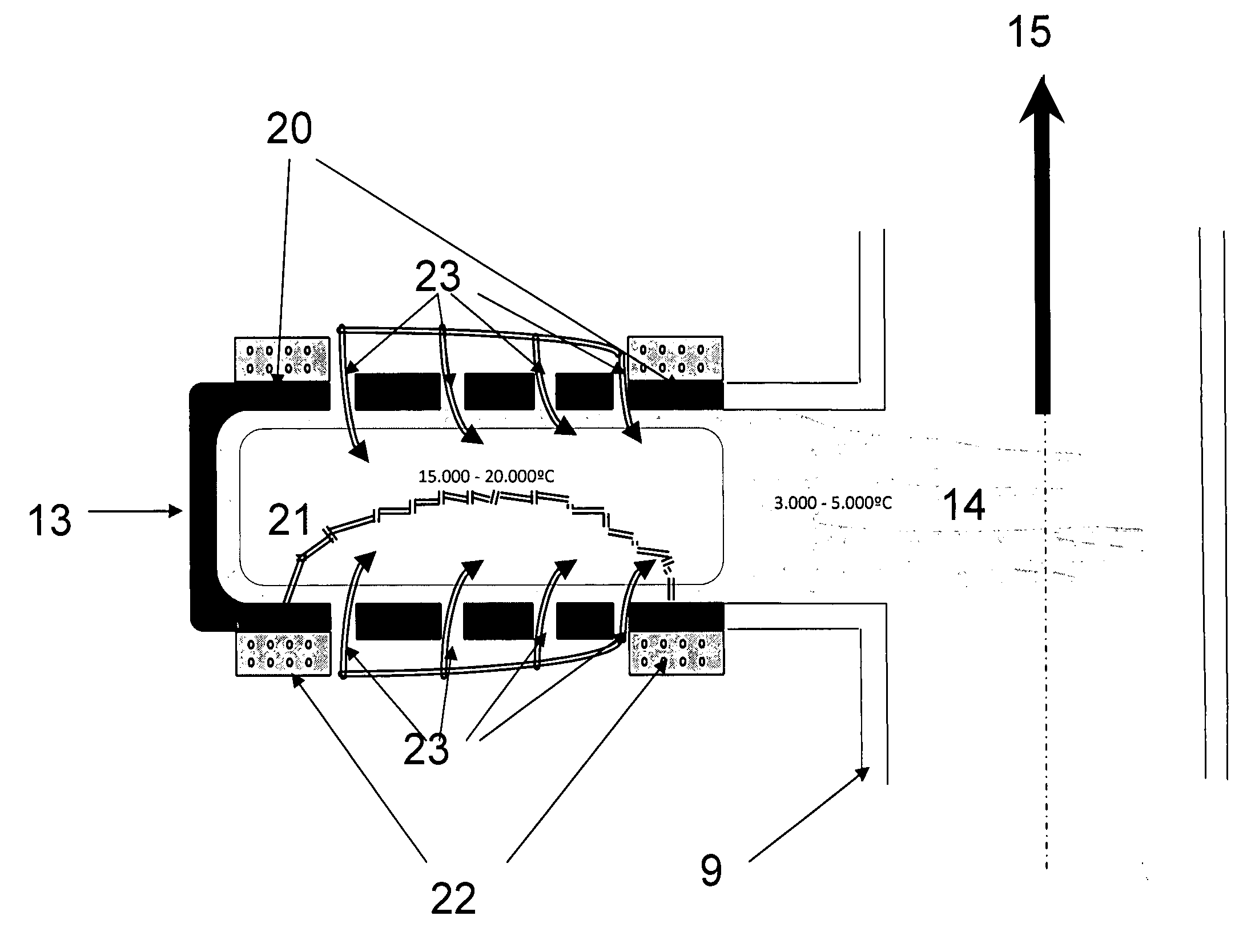
[0048]The invention will be verified and described in further detail by providing an example of an embodiment carrying out the method according to the invention. This embodiment should not be considered as a limitation of the general inventive idea of decomposition and subsequent condensation to convert all organic including halo-organic compounds in the syngas to low-molecular anaerobic combustion products. Any combination of gasifier, heat treatment device able to heat the raw syngas to at least 1250° C. and then rapidly condensate the atomised gas / plasma gas to low molecular anaerobic combustion products, and Fischer-Tropsch reactor are within the inventive scope of this invention.

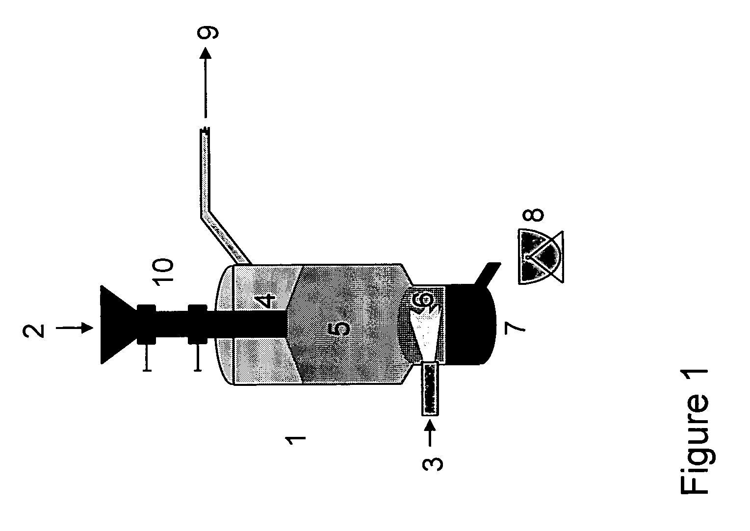
[0049]The gasifier according to the example embodiment of the invention is a counter counter-current-flow shaft as shown in FIG. 1. This gasifier 1 comprises a waste / biomass inlet 10 with a two-port sluice system for introduction of waste / biomass 2 in the upper region 4 of the gasifier 1...


PUM

PropertyMeasurementUnit
Temperatureaaaaaaaaaa

Abstract

The invention concerns a method and a plant for producing hydrocarbon based fuels from waste and biomass including wood and/or other cellulose containing biomass, where biomass and/or waste is gasified in anaerobic conditions, heating the formed syngas in for decomposition and subsequent condensation in anaerobic conditions, subjecting the heat treated biosyngas to cleaning measures for removing elements/compounds which are poisonous towards the catalysts of the Fischer-Tropsch synthesis, and passing the cleaned heat treated biosyngas through a Fischer-Tropsch synthesis for production of biofuels.

Description

[0001]The invention concerns a method and a plant for producing hydrocarbon based fuels from waste and biomass including wood and / or other cellulose containing biomass.BACKGROUND[0002]The Intergovernmental Panel of Climate Change has recently released its fourth assessment report on climate change (IPCC 4AR), stating with very high confidence that human activities results in a climate forcing that may give dangerously strong climate changes in many regions of the world unless there is introduced substantial decreases in the emissions of greenhouse gases, especially carbon dioxide in the coming decades. The scientific discoveries and climate forcing knowledge expressed in IPCC 4AR is expected to result in both international agreements and national decisions for restrictions on emissions of carbon dioxide of fossil origin in the coming years.[0003]One of the major contributing sectors of carbon dioxide emissions in developed countries is the transport sector, which presently is almost...

Claims


Application Information

Patent Timeline
IPC IPC(8): C07C27/06B01J19/08
CPCC10B49/04Y02E50/32C10G2/30C10J3/08C10J3/20C10J3/66C10J2200/156C10J2300/0916C10J2300/0946C10J2300/0956C10J2300/1238C10J2300/1634C10J2300/1659C10J2300/1671C10J2300/1675C10J2300/1846C10K1/002C10K1/003C10K1/004C10K1/02C10K1/024C10K1/028C10K1/101C10K1/143C10K1/32C10K3/04F23G2201/40F23G2204/201F23G2207/30F23G2209/26F23G2900/50208Y02E50/14C10B53/02Y02E50/10Y02E50/30Y02P20/129Y02P20/145
Inventor TONSETH, ERIK
Owner TONSETH ERIK
Why Eureka
Try Eureka