System and method for powering an aircraft using radio frequency signals and feedback

Active Publication Date: 2010-09-09
REARDEN
View PDF18 Cites 61 Cited by
  • Summary
  • Abstract
  • Description
  • Claims
  • Application Information

AI Technical Summary

Benefits of technology

[0040]A system and method are described for powering an aircraft using radio frequency (“RF”) signals. For example, a method according to one embodiment of the invention comprises: positioning an antenna array beneath or on the road surface of a roadway, the antenna array configured to transmit RF signals responsive to RF processing logic and/or circuitry; coupling a rectenna array to an aircraft, the rectenna array configured to receive the RF signals transmitted from the antenna array and to generate power from the RF signa

Problems solved by technology

The world's heavy reliance on fossil fuels for vehicular power has resulted in a number of problems and concerns.
IC engine emissions, despite increasingly stringent controls in many countries, contribute significantly to air pollution and release significant quantities of carbon dioxide, potentially harming the ozone layer and/or contributing to global warming.
Many of the world's largest reserves of fossil fuels are in politically unstable areas of the world.
Once the milestone event of peak supply and rapid depletion occurs, the cost of fossil fuel is likely to rise dramatically, further worsening the ongoing practicality for society to rely largely on fossil fuels.
However, with fossil fuel-powered vehicles the energy choices are limited to fossil fuels such as gasoline, diesel, and natural gas that are in liquid or gaseous form and are highly portable.
Of course, it is a complex analysis to compare an electric vehicle's overall efficiency to a gasoline vehicle's, but generally speaking, the energy costs for electric vehicles are less expensive per mile compared to similar gasoline vehicles.
Each prior art system developed and/or proposed in the last century to reduce fossil fuel dependence has its advantages and disadvantages, but to date, none has provided a solution which has the convenience and efficiency of a modern IC-powered automobile and offers a long-term solution that elimin

Method used


Image

  • System and method for powering an aircraft using radio frequency signals and feedback
  • System and method for powering an aircraft using radio frequency signals and feedback
  • System and method for powering an aircraft using radio frequency signals and feedback

Examples


Example

[0065]Described below is an improved apparatus and method for powering a vehicle. In the following description, for the purposes of explanation, numerous specific details are set forth in order to provide a thorough understanding of the present invention. It will be apparent, however, to one skilled in the art that the present invention may be practiced without some of these specific details. In other instances, well-known structures and devices are shown in block diagram form to avoid obscuring the underlying principles of the invention.

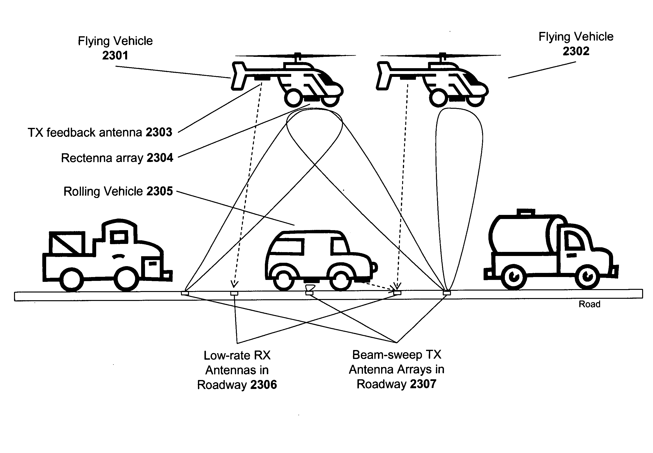
[0066]One embodiment of the invention powers a vehicle using wireless radio frequency signals transmitted from an antenna embedded within a roadway to a rectenna on the vehicle. The rectenna may be positioned on the underbody of the vehicle and may be configured to receive the RF signals as the vehicle passes over the transmitting antenna.

[0067]FIG. 9 illustrates one embodiment which includes an RF generator unit 171 positioned beneath the road surf...


PUM


Abstract

A system and method are described for powering an aircraft using radio frequency (“RF”) signals. For example, a method according to one embodiment of the invention comprises: positioning an antenna array beneath or on the road surface of a roadway, the antenna array configured to transmit RF signals responsive to RF processing logic and/or circuitry; coupling a rectenna array to an aircraft, the rectenna array configured to receive the RF signals transmitted from the antenna array and to generate power from the RF signals; providing feedback signals from the aircraft to the RF processing logic and/or circuitry, the feedback signals including channel state information (CSI) defining a current state of the channels between the antenna array and the rectenna array, the RF processing logic and/or circuitry using the channel state information to adjust the RF signal transmissions from the antenna array to improve the efficiency of the power generated by the rectenna array; and using the power generated by the rectenna array to power the aircraft.

Description

CLAIM OF PRIORITY[0001]This application is a continuation in part of application Ser. No. 11 / 136,946 filed May 24, 2005.BACKGROUND OF THE INVENTION[0002]1. Field of the Invention[0003]This invention relates generally to the field of vehicle propulsion systems. More particularly, the invention relates to an improved system and method for powering a vehicle using radio frequency signals.[0004]2. Description of the Related Art1. Introduction[0005]Developing vehicles which reduce reliance upon fossil fuels is a matter of critical global importance. Fossil fuels (e.g., gasoline, diesel fuel, natural gas) are used in the vast majority of vehicles in the world because of fossil fuels' high energy density, fast refueling time, relatively low cost, and the maturity of internal combustion (“IC”) engines that run on fossil fuels.[0006]The world's heavy reliance on fossil fuels for vehicular power has resulted in a number of problems and concerns. IC engine emissions, despite increasingly strin...

Claims


Application Information

Patent Timeline
IPC IPC(8): B64C39/00
CPCB60K6/46B60L9/00B60L11/1816B60L11/182B60W2510/244B60L2200/26Y02T10/6269Y02T10/7005Y02T90/122Y02T90/14Y02T10/6217B60L50/53B60L53/124B60L53/14Y02T10/62Y02T10/70Y02T10/7072Y02T90/16Y02T90/12
Inventor PERLMAN, STEPHEN G.FORENZA, ANTONIO
Owner REARDEN
Why Eureka
Try Eureka