
Affinity capture mass spectroscopy with a porous silicon biosensor

a biosensor and porous silicon technology, applied in the field of mass spectroscopy and optical biosensors, can solve the problems of inability to achieve mass spectroscopy. the effect of high degree of freedom

Inactive Publication Date: 2010-09-09
SILICON KINETICS
View PDF9 Cites 22 Cited by
  • Summary
  • Abstract
  • Description
  • Claims
  • Application Information

AI Technical Summary

Benefits of technology

[0023]The present invention is an analytical process for making molecular ligand-analyte binding measurements when the analyte is unknown. The process couples the sensitivity of a label-free binding detected biosensor, and the information richness of mass spectroscopy. A 3-dimensional porous silicon bio-surface is used to captur

Problems solved by technology

In addition to the optical biosensors discussed above, scientists perform kinetic binding measurements using other separations methods on solid surfaces combined with expensive detection methods (such as capillary liquid chromatography / mass spectrometry) or solution-phase assays.
These methods suffer from disadvantages of cost, the need for expertise, imprecision and other factors.
These SPR sensors are typically very expensive.
As a result, the technique is impractical for many applications.
There have been attempts to combine SPR with mass spectroscopy (SPR-MS, see below) but these invariably suffer from the low capture capability of the planar SPR surfaces and could not be directly coupled to an electrospray mass spectrometer as described here with AC-MS.
This prism requirement has generally precluded SPR from being economically viable on a per-well basis.
That is, SPR has not been economically adapted to measuring data directly in a microtiter well plate.
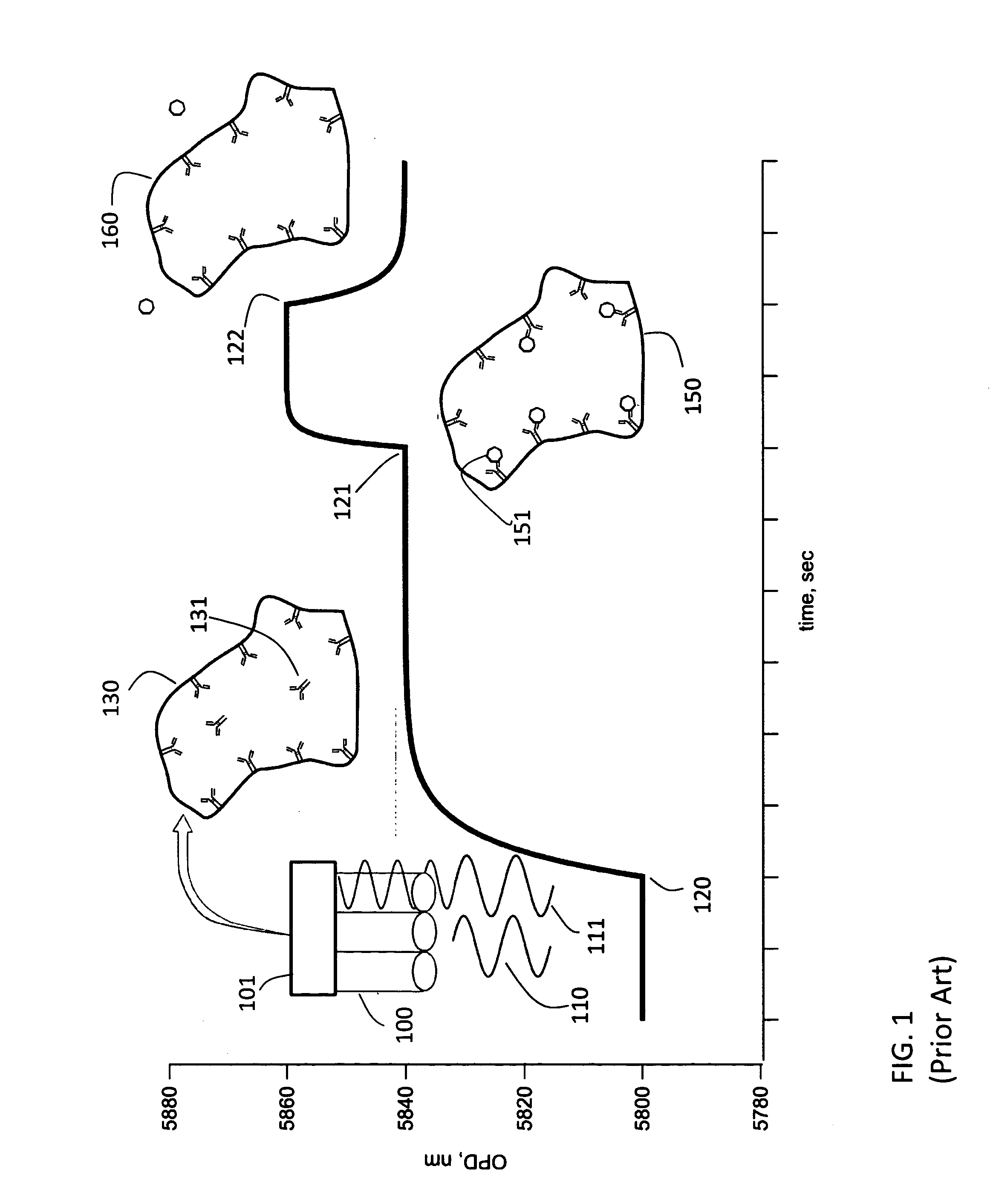
But an experiment where, for instance, the analyte flowing across an immobilized ligand is not known, one could still measure the kinetic constants and affinity of the measurement, but typically the biosensor instrument could not identify the compound.
This technique suffers from the low binding capacity of the planar SPR surface and has generally been limited to only MALDI detected mass spectroscopy in practice due to this limited capability.
Nelson et al. do not teach the coupling of NPOI with mass spectroscopy in both plate reading and flow cell modes.

Method used


Image

  • Affinity capture mass spectroscopy with a porous silicon biosensor
  • Affinity capture mass spectroscopy with a porous silicon biosensor
  • Affinity capture mass spectroscopy with a porous silicon biosensor

Examples


first preferred embodiment

Flow Cell with Electrospray and Fraction Collection

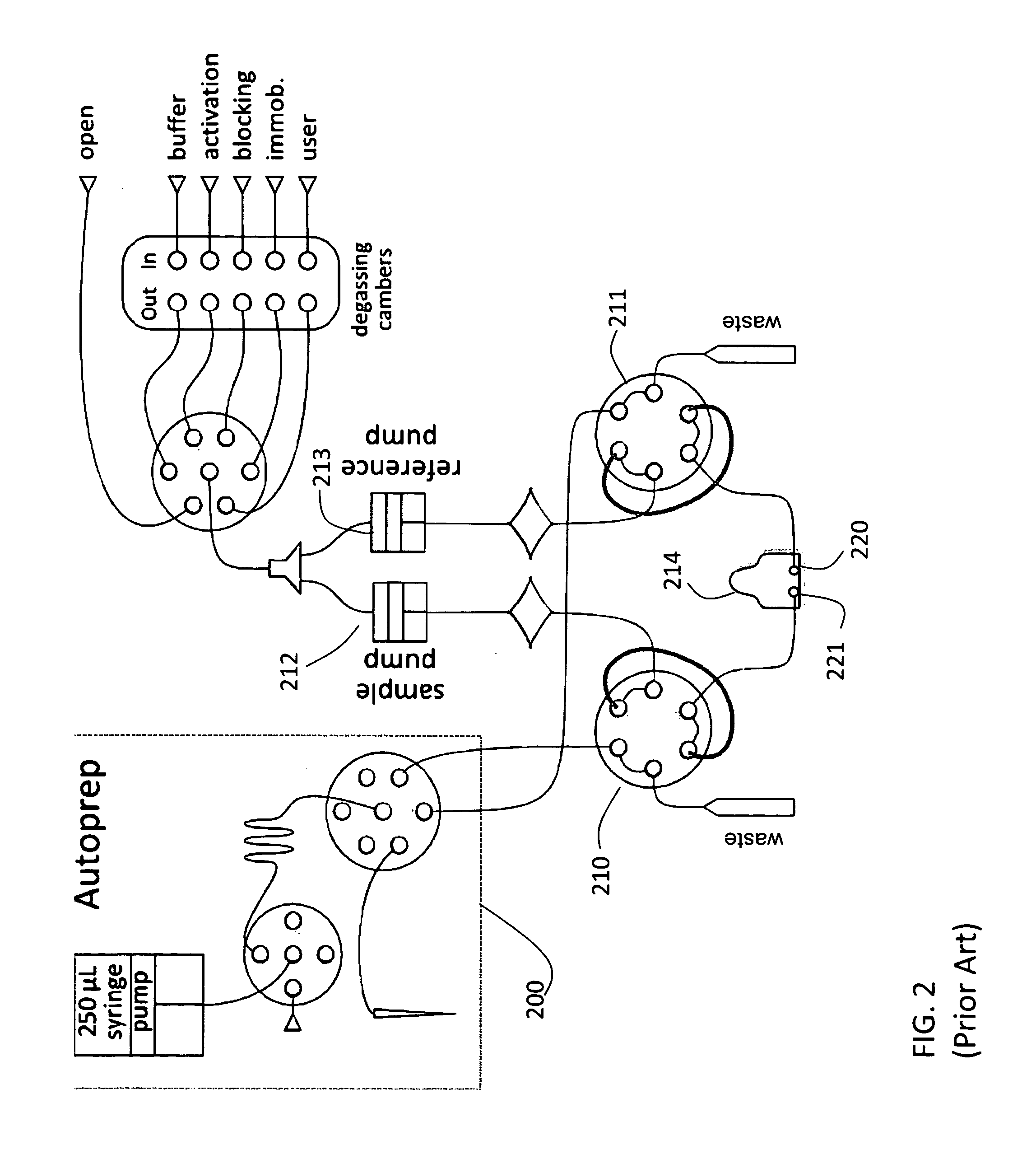
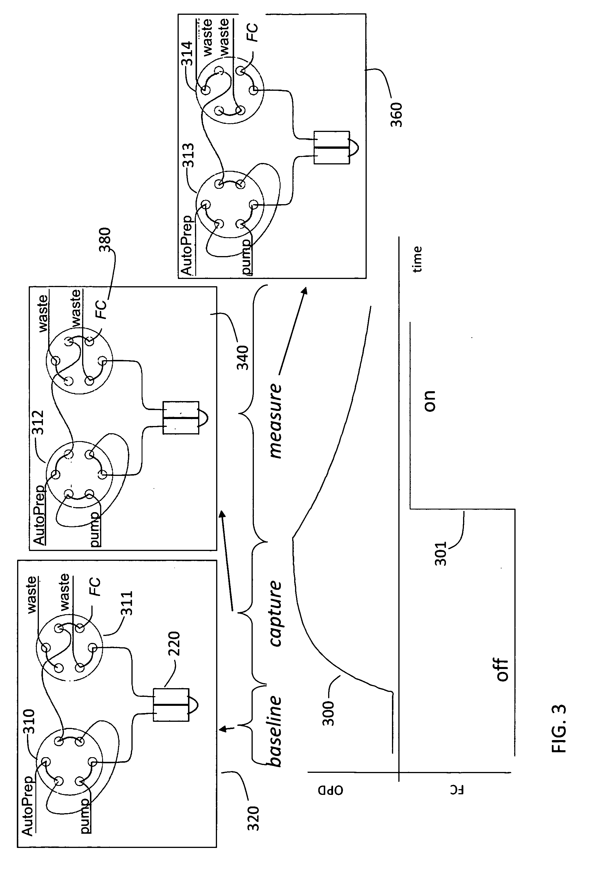
[0055]The first embodiment is sketched in FIG. 3. The NPOI flow cell instrument is used together with a fraction collector. This fraction collector could simply be a collection vessel of some sort. Initially capture molecule is placed on the porous silicon chip using a typical flow cell procedure. A carboxyl chip shown at 214 in FIG. 2, used for amino coupling, is used. This contains both a sample and reference channel 220 and 221. Using the AutoPrep 200 and two 6-port, 2-position injection valves, one for the sample 210 and one for the reference 211, solutions are introduced to the flow cell. Initially the chip is activated using water as running buffer, pumped by two separate pumps one for sample 212 and one for reference 213, at 8 μL / min. A solution of 200 mM, 1-ethyl-3-(3-dimethylaminopropyl) carbodiimide (EDC) and 50 mM sufo N-hydroxysuccinimide (sNHS) is used to activate the chip for 8 minutes. Then a solution of 20 μg / mL capt...

second preferred embodiment

Flow Cell with Electrospray and Direct Elution

[0058]The second preferred embodiment is sketched in FIG. 4. Similar to the first embodiment, this second embodiment replaces the fraction collection output with an input directly into the mass spectrometer. Here, capture agent is immobilized as before and binding is initiated as before by a switch in the sample injection valve from the loading position with valves as shown at 420 to the inject position (440), however in this case binding buffers must be compatible with mass spectrometer ionization. The output to the mass spectrometer is sent into a y-union (not shown) in which a 0.1% formic acid in methanol mixture is added to the eluent from the flow cell device in order to aid electrospray ionization.

[0059]A specific example of such an approach is shown in FIG. 9. Here carbonic anhydrase II (CAII) (the ligand), an enzyme from bovine erythrocytes, is immobilized on the carboxyl chip at 100 μg / mL for 15 minutes. Furosemide (the analyte)...

third preferred embodiment

Flow Cell with Electrospray and LC Trap and Elute

[0062]The third preferred embodiment is sketched in FIG. 5. This differs from the first and second embodiment in that a trap chromatography column 530 is placed on the reference side injection valves, a C18 packing is used in a 2.7 μM4 Opti-Pak trap from Optimize technologies (Oregon City, Oreg.). In this embodiment, the enrichment phase 520 proceeds as before with the sample injection valve sampling routing the flow cell eluent to waste while a liquid chromatography device (e.g. an Agilent 1100, Agilent Corporation, Santa Clara, Calif.) attached to the reference injection valve configured as shown at 532 flows water across the trap into a mass spectrometer (not shown). However, during capture, when conditions become dissociative, the reference injection valve configured as shown at 533 now switches to route the flow cell eluent onto the trap column. The trap column will then trap the reagent flowing across from the cell. This occurs ...


PUM


Abstract

Affinity Capture-Mass Spectroscopy (AC-MS), an analytical technique which couples the sensitivity of a label-free binding detected biosensor, and the information richness of mass spectroscopy is described. A 3-dimensional porous silicon bio-surface is used to capture proteins, DNA, or small molecules while acquiring a label-free, time resolved signal linearly proportional to the amount of binding. A switch to dissociative buffer conditions then frees the captured molecule for analysis by mass spectroscopy. In particular, techniques for use with electrospray mass spectroscopy are described.

Description

CROSS-REFERENCE TO RELATED APPLICATIONS[0001]This application claims the benefit of Provisional Application Ser. No. 61 / 209,416 filed 03-05-2009, entitled Mass Spectroscope with Porous Silicon Flow Cell.FIELD OF INVENTION[0002]This invention relates to mass spectroscopy and optical biosensors and in particular to porous silicon biosensors.BACKGROUND OF THE INVENTIONOptical Biosensors[0003]An optical biosensor is an optical sensor that incorporates a biological sensing element. In recent years optical biosensors have become widely used for sensitive molecular binding measurements. To study interactions of proteins with other biomolecules one may generally use labeled or label-free methods. For these methods a first molecule of interest (a receptor, also referred to as a ligand) is immobilized onto a surface. An interaction is monitored by then introducing additional molecules (a target, also referred to as an analyte) and detecting whether they in fact bind to the receptor. When usin...

Claims


Application Information

Patent Timeline
IPC IPC(8): G01N33/566
CPCG01N33/6848
Inventor ERVIN, JOHN LAWRENCE
Owner SILICON KINETICS
Learn More