Lithographic machine platform and applications thereof

Inactive Publication Date: 2010-09-16
NAT APPLIED RES LAB
View PDF7 Cites 0 Cited by
  • Summary
  • Abstract
  • Description
  • Claims
  • Application Information

AI Technical Summary

Benefits of technology

[0008]Further objective of the present invention is to provide a lithographic machine platform and application thereof, wherein not only number of the steps of the lithographic fabrication process and the fab

Problems solved by technology

On the contrary, the existing advanced immersion lithography is moistene

Method used


Image

  • Lithographic machine platform and applications thereof
  • Lithographic machine platform and applications thereof
  • Lithographic machine platform and applications thereof

Examples


Example

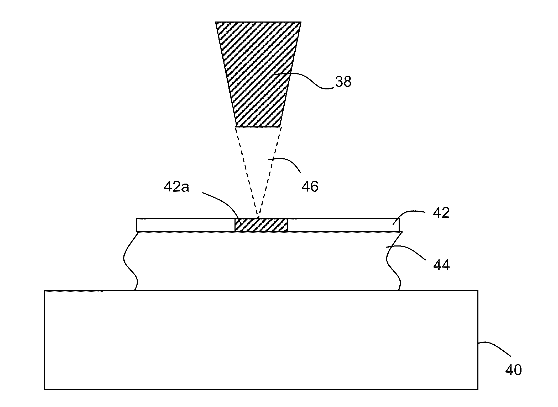
[0022]The spirit of the present invention relates to a lithographic machine platform and applications thereof, which forms a patterned layer used as a hard mask layer or other applications on a substrate by using the high lithographic properties of an electron beam or an ion beam. According to the above-mentioned description, the utilization and selection of the material of a precursory thing and a patterned layer, or the variations of process parameters are both within a spiritual scope of the present invention.

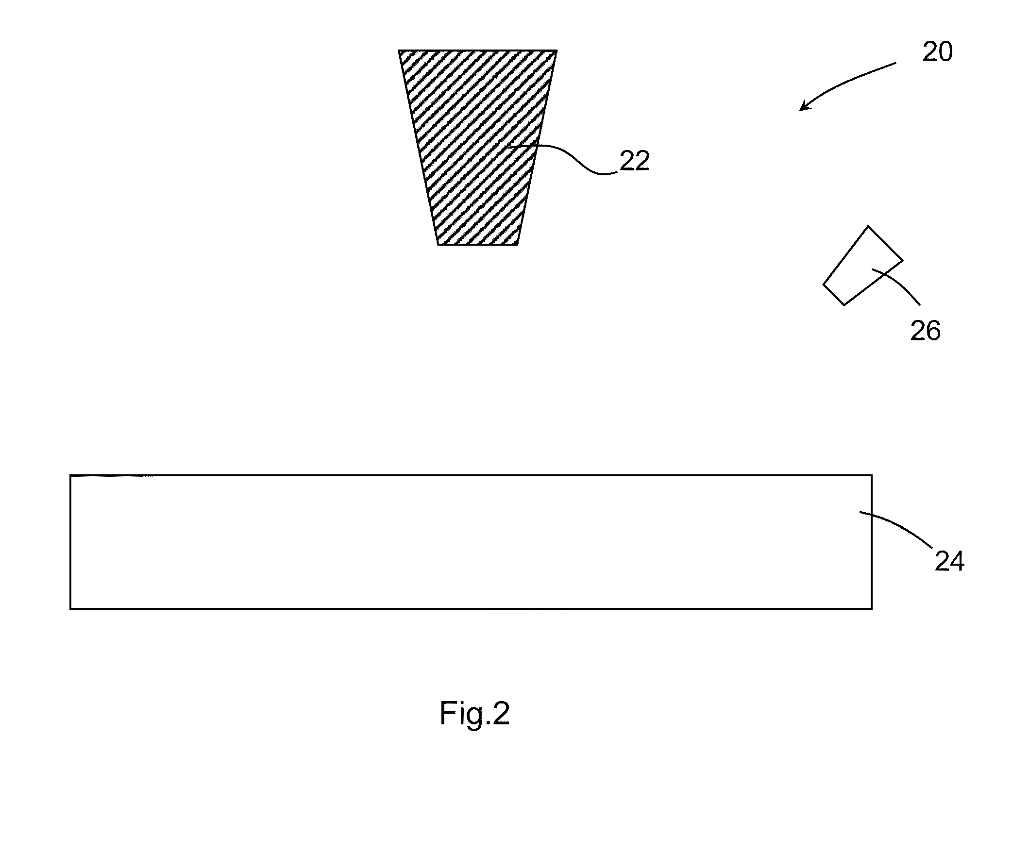
[0023]Refer to FIG. 2, which are diagrams schematically showing the first configuration of the lithographic machine platform according to the present invention. As shown in FIG. 2, an electron beam or an ion beam lithographic machine platform 20 of the present invention comprises: an electron beam or an ion beam generator 22; a substrate supporting platform 24 positioned below the electron beam generator or the ion beam generator 22; and a precursory gas injector 26 injectin...


PUM

PropertyMeasurementUnit
Dielectric polarization enthalpyaaaaaaaaaa
Metallic bondaaaaaaaaaa

Abstract

A lithographic machine platform and applications thereof is disclosed. The lithographic machine platform comprises: an electron beam or an ion beam generator generating an electron beam or an ion beam; a substrate supporting platform supporting a substrate; and a precursory gas injector injecting a precursory gas above the substrate. The present invention uses the electron beam or the ion beam to induce the precursory gas to react with the electron beam or the ion beam, and then the precursory gas is deposited on the substrate. The present invention not only fabricates a patterned layer on the substrate in a single step but also achieves a high lithographic resolution and avoids remains of contaminations by using the properties of the electron beam or the ion beam and the precursory gas.

Description

BACKGROUND OF THE INVENTION[0001]1. Field of the Invention[0002]The present invention relates to a lithographic technology, particularly to an electron beam or ion beam lithographic machine platform and applications thereof, which is applied to the lithographic technology.[0003]2. Description of the Related Art[0004]Presently, in a advanced lithographic fabrication process, patterns are generated by using an optical method, an electron beam, a nano impression method on a specific polymer coating layer (namely, the polymer material that is sensitive to lights or electron beams), also called resist, through chemical reactions or variations of thermal current stress and then used as a required mask when the subsequent pattern is transferred. But the resist usually requires complicated thermal treatment, exposure and development or the hull release fabrication process. Besides, for the lithography technology with a high resolution, a thickness of the resist is not enough for consumption...

Claims


Application Information

Patent Timeline
IPC IPC(8): B32B3/02G03F7/20C23C16/448B32B3/10B01J19/08
CPCC23C14/048C23C16/047H01L21/0337H01L21/31105H01L21/3213Y10T428/24802G03F7/2022G03F7/203G03F7/2059Y10T428/24612G03F7/20
Inventor HUANG, CHIEN-CHAOCHEN, CHUN-CHISHY, SHYI-LONGWU, CHENG-SANYANG, FU-LIANG
Owner NAT APPLIED RES LAB
Why Eureka
Try Eureka