Method and Apparatus for Estimating Rotor Position in a Sensorless Synchronous Motor
- Summary
- Abstract
- Description
- Claims
- Application Information
AI Technical Summary
Benefits of technology
Problems solved by technology
Method used
Image

Examples
first embodiment
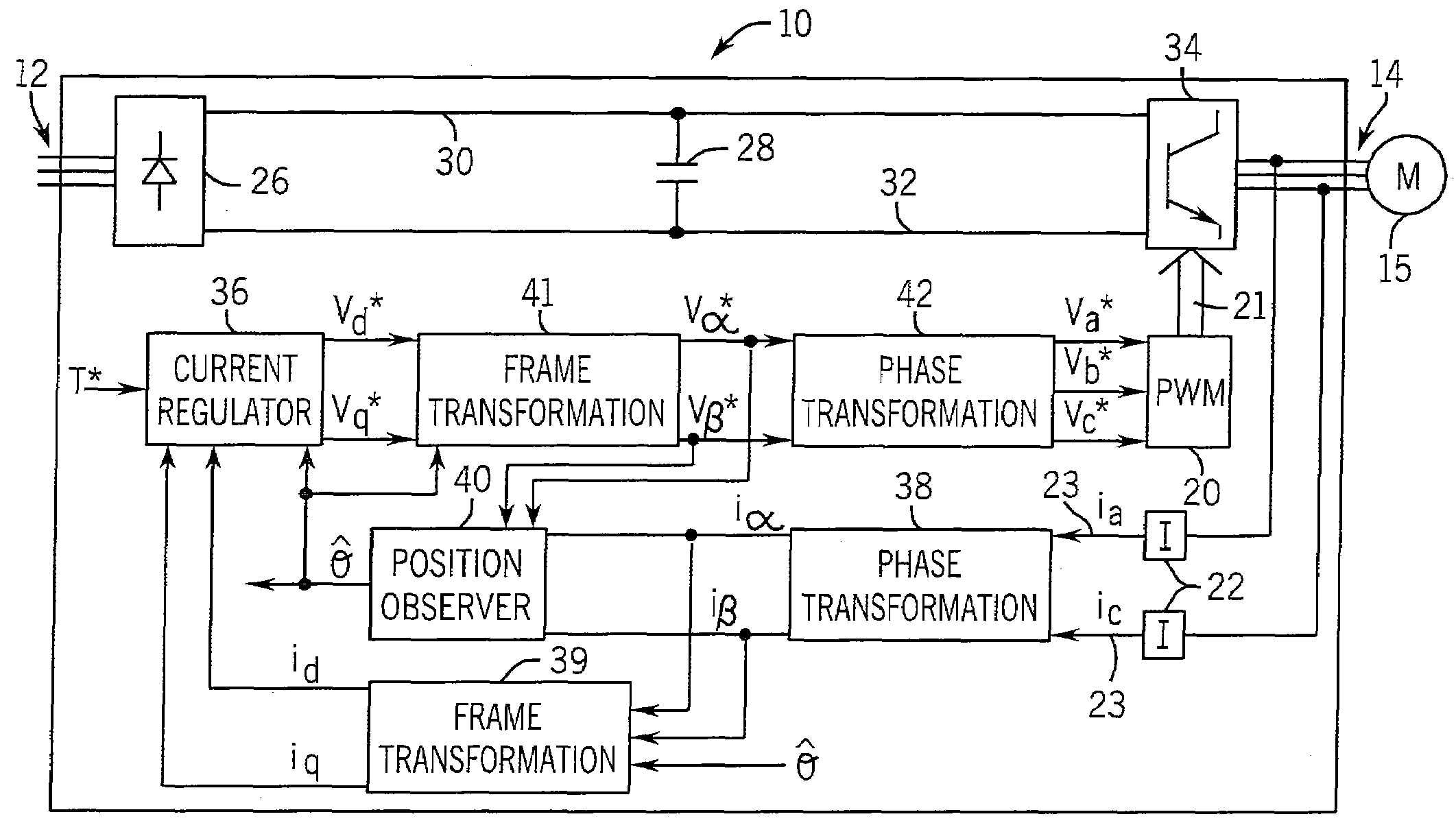
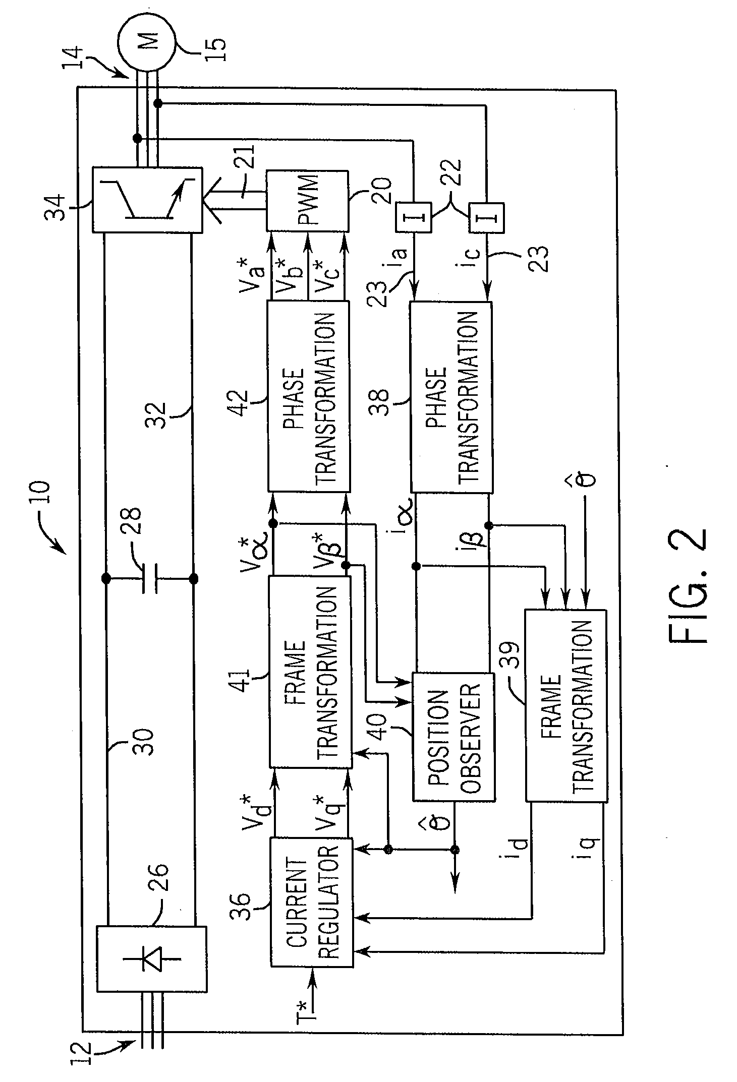
[0038]Referring next to FIGS. 3-5, the position observer 40 according to the present invention is illustrated. The current feedback (iα and iβ) and voltage signals (vα and vβ), each in the stationary reference frame, are inputs to the position observer 40. The position observer 40 uses a model 44 of a synchronous motor to calculate equivalent EMF values in the stationary reference frame (e′α and e′β) as developed according to equations (1)-(8).
[0039]The model 44 is based on a voltage model of a permanent magnet salient pole synchronous machine in the stationary reference frame, equation (1). Current feedback signals (iα and iβ) and voltage signals (vα and vβ) in the stationary reference frame are input to the position observer 40. These current and voltage signals are used by the EMF model 44, equation (6), to determine the equivalent EMF values (e′α and e′β). The equivalent EMF values are then inputs to block 46 and used to estimate the rotor position, {circumflex over (θ)}.
[vαvβ]=...
second embodiment
[0046]Referring now to FIGS. 6-8, the position observer 40 according to the present invention is illustrated. The motor current and voltage, each being transformed to the stationary reference frame, are input signals to the position observer 40. The position observer 40 uses a sliding mode model 54 and an equivalent control block 56 to obtain an estimated rotor position, {circumflex over (θ)}.
[0047]Sliding mode control is a non-linear control strategy which attempts to force a dynamic system to operate at a desired operating point using a “bang-bang” type controller. A “bang-bang” type controller compares an input signal against a pre-determined operating point, for example a particular value or plane of operation, and outputs one of two values, for example a zero or a one, based on which side of the operating point the input signal is located. A set of sliding mode equations is developed according to principles of sliding mode control, and the equations are used to force desirable ...
PUM
 Abstract
Description
Claims
Application Information