Analytical strip and the manufacturing method thereof

a technology of analytical strips and manufacturing methods, applied in the field of analytical strips, can solve the problems of fluid sample waste, fluid sample waste, and inability to fully react to the surface of the channel, and achieve the effects of low residual sample volume, constant volumetric absorption capacity, and low residual sample volum

Inactive Publication Date: 2010-09-23
ACTHERM INC
View PDF17 Cites 9 Cited by
  • Summary
  • Abstract
  • Description
  • Claims
  • Application Information

AI Technical Summary

Benefits of technology

[0009]Hence, the primary object of the present invention is to provide an analytical strip comprising the channel with hollow-matrix conformation. The channel thus has lower residual of samples in contrast to the traditional microfluidic channel, and low volume of samples needed for multi-analytes detection in a test is realized.
[0010]Another object of the present invention is to provide an analytical strip that comprises absorptive nitrocellulose layers having a constant volumetric absorptive capacity and thus allows a quantitative assay to be conducted via controlling the volume of the nitrocellulose layers.
[0011]Still another object of the present invention is to provide an analytical strip that has absorptive nitrocellulose layers with a hollow-matrix configuration, which is capable of destroying the air bubbles in the fluid sample when the fluid sample flows through the hollow matrix, as well as preventing the bubbles from blocking the channel or the microfluidic channel of the substrate. Thus, an accurate result of the quantitative assay could be assured.
[0012]Yet another object of the present invention is to provide an analytical strip comprising the channel formed on the flat surface of the substrate in the predetermined pattern, instead of using molding, injection forming, imprint or using expensive die making process such as micro-machining or lithography-electroforming-micro-molding, thus saving costs for mass manufacture of the analytical strip.
[0013]A further object of the present invention is to provide a manufacturing method that can produce an analytical strip of a reduced manufacturing cost and an improved measuring accuracy.

Problems solved by technology

Since the channels are bordered by non-absorbent material, and fluid samples to be tested are usually viscous compositions containing, for example, protein or carbohydrate, a fluid sample flowing in the channels tends to adhere to surfaces of the channels and cannot be fully reacted.
Consequently, the fluid sample is wasted, if not leading to errors of test results.
These bubbles, when causing channel blockage, may result in test errors or even test failure.
Moreover, installation of the micro-actuators or micro-valves will add to the overall difficulty of design and the cost of analytical strips.
Besides, during manufacture of the conventional analytical strips, the channels or microfluidic-channels are usually formed on the substrates by micro-injection forming or imprinting, using expensive die making process such as micro-machining or LIGA (abbreviation of “Lithographie GalVanoformung Abformung”, or “Lithography Electroforming Micro Molding” in English) which, coupled with early wear and tear of molds, increases the total cost incurred in making analytical strips.
Hence, the residual of the fluid sample in the channel renders testing inconvenient and time-consuming.
In addition, the manufacturing cost of traditional analytical strip is usually considerable.

Method used


Image

  • Analytical strip and the manufacturing method thereof
  • Analytical strip and the manufacturing method thereof
  • Analytical strip and the manufacturing method thereof

Examples


first embodiment

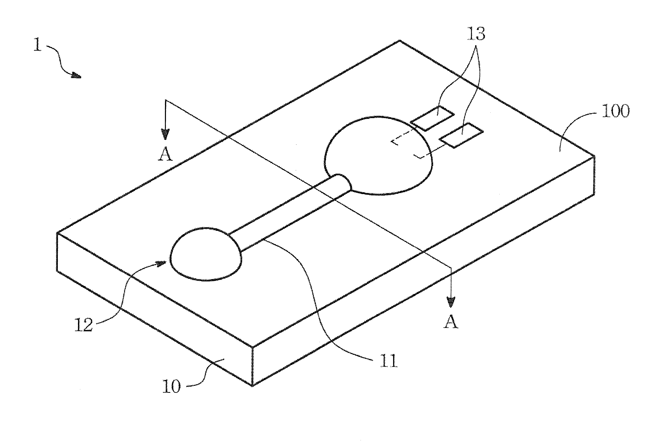
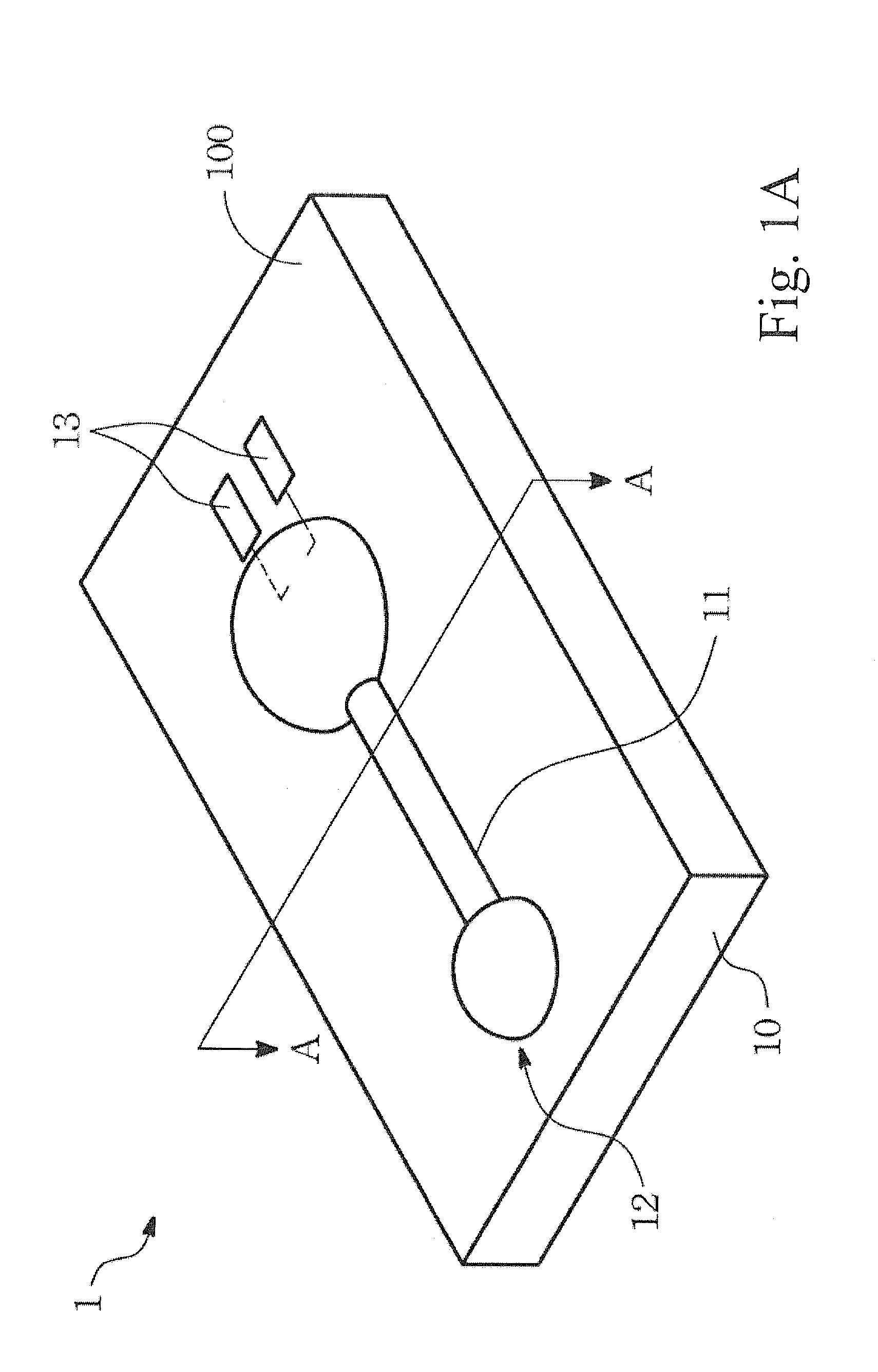
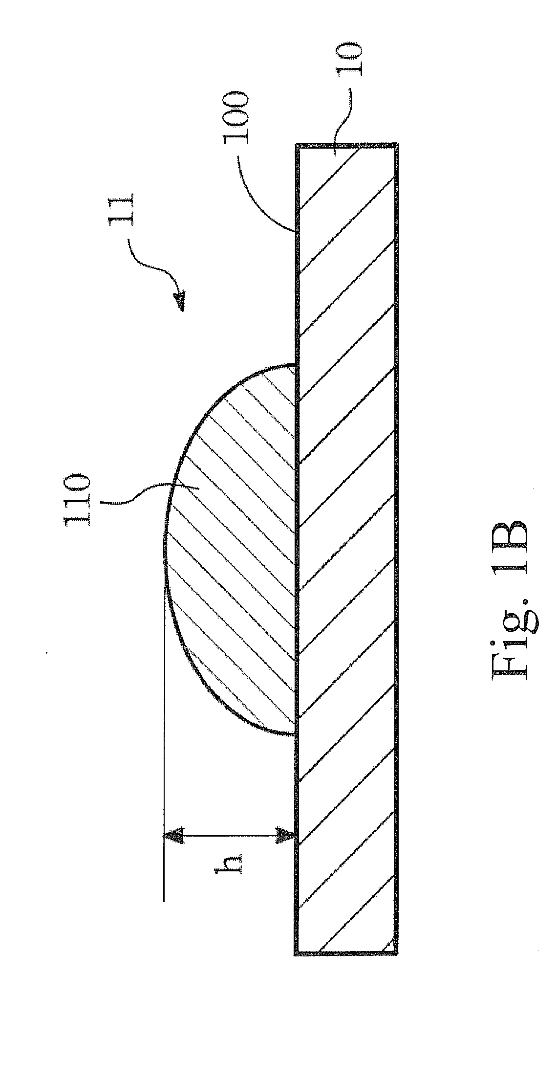
[0023]Please refer to FIG. 1A for an analytical strip according to the present invention. The analytical strip 1 includes a substrate 10 and a channel structure 11. The substrate 10 has a flat surface 100, and the channel 11 is formed on the flat surface 100 of the substrate 10 according to a predetermined pattern 12. The surface of the channel 11 is not lower than the flat surface 100 of the substrate 10. In addition, the channel 11 has a hollow-matrix conformation and the channel 11 is more hydrophilic than the flat surface 100 of the substrate 10 is. For making the channel 11, a high-hydrophilic solution is applied to the flat surface 100 of the substrate 10 by means of lithographic printing, photogravure, anastatic printing, screen-printing, line marking, inkjet / spray, casting, or dipping.

[0024]The solution that is applied to the flat surface 100 of the substrate 10 may contains nitrocellulose or fiberglass, so that after dried and solidified the channel 11 is formed with porous...

third embodiment

[0042]The third preferred embodiment of the present relates to an alternative manufacturing method of the analytical strip. Please refer to FIGS. 3A and 3B. FIG. 3A is a flow chart of the manufacturing method of the present invention. FIG. 3B shows the analytical strip in the process of the manufacturing method of the present embodiment.

[0043]The manufacturing method of the analytical strip of the present embodiment primarily comprises the following steps:

[0044]Step 31: Firstly providing a substrate 30 that has a flat surface 300.

[0045]Step 32: Providing a mask 33 that is engraved with a predetermined pattern 32.

[0046]Step 33: Adhering the mask 33 detachably to the substrate 30.

[0047]Step 34: Providing a solution and fill the engraved predetermined pattern 32 with the solution.

[0048]Step 35: Drying the solution filled in the predetermined pattern 32.

[0049]Step 36: Removing the mask 33 to form a channel 31 that has the predetermined pattern 32. The surface of the dried channel 31 is ...


PUM


Abstract

An analytical strip including a substrate and a channel structure is disclosed. A substrate has a flat surface and the channel is formed on the flat surface according to a predetermined pattern. The surface of channel structure is not lower than the surface of the substrate. The channel has a hollow-matrix conformation and the channel is more hydrophilic than the flat surface of the substrate is. The strip also contains a reaction material formed in the hollow-matrix.

Description

BACKGROUND OF THE INVENTION[0001]1. Technical Field[0002]The present invention relates to analytical strips and more particularly, to an analytical strip for biochemical and immunological assays.[0003]2. Description of Related Art[0004]Analytical strips are conventionally used in biochemical tests and immunological tests. A typical analytical strip has a substrate or a base formed with sunken channels or micro-channels and processed with hydrophobic and hydrophilic surface treatment. Since the channels are bordered by non-absorbent material, and fluid samples to be tested are usually viscous compositions containing, for example, protein or carbohydrate, a fluid sample flowing in the channels tends to adhere to surfaces of the channels and cannot be fully reacted. Consequently, the fluid sample is wasted, if not leading to errors of test results.[0005]In addition, the conventional analytical strips are provided with micro-channels to facilitate fluid delivery, in which the micro-chan...

Claims


Application Information

Patent Timeline
IPC IPC(8): C12M1/00G01N33/53G01N33/531B05D5/00
CPCG01N33/54366C12Q1/25G01N33/53G01N33/68
Inventor HSIEH, WEI-PINTSENG, CHING-TAICHEN, JUI-TSE
Owner ACTHERM INC
Why Eureka
Try Eureka