Pressure casting of electric rotors

a technology of electric rotors and pressure casting, which is applied in the direction of synchronous motors, foundry patterns, foundry moulding apparatuses, etc., can solve the problems related gas entrapment in the relatively in the end rings, and in the relative long but narrow passages. , the squirrel cage rotor casting is either difficult to achieve, and the effect of high molten flow turbulen

Inactive Publication Date: 2010-09-30
GM GLOBAL TECH OPERATIONS LLC
View PDF5 Cites 26 Cited by
  • Summary
  • Abstract
  • Description
  • Claims
  • Application Information

AI Technical Summary

Benefits of technology

[0018]Optionally, heating the laminate stack may be done with either a uniform temperature along the stack, or may be done with a temperature gradient along the stack length. In either case, an inductive heating device (such as an inductive heating rod) can be used to impart heat to the laminate stack. In another option, the temperature is maintained at least about 800 degrees Fahrenheit for premium grade castings. Moreover, the amount of pressure deemed to be sufficient is at le

Problems solved by technology

Unfortunately, either of these forms of squirrel-cage rotor casting suffers from drawbacks.
Such pressures, while promoting fast (on the order of a tenth of a second) fill time, also result in high molten flow turbulence and related gas entrapment in the relatively long but narrow passages and in the end rings.
Because the performance of squirrel-cage rotors is closely related to the electrical continuity between the bars and the end rings, such porosity is undesirable.
Equally problematic is the impact that porosity has on the mechanical properties of the cast rotor, again especially at the end remote from the mold gating and related fluid introduction.
When such aluminum in molten form comes in contact with the tooling-grade steel of a die cast or squeeze tooling die se

Method used


Image

  • Pressure casting of electric rotors
  • Pressure casting of electric rotors
  • Pressure casting of electric rotors

Examples


Embodiment Construction

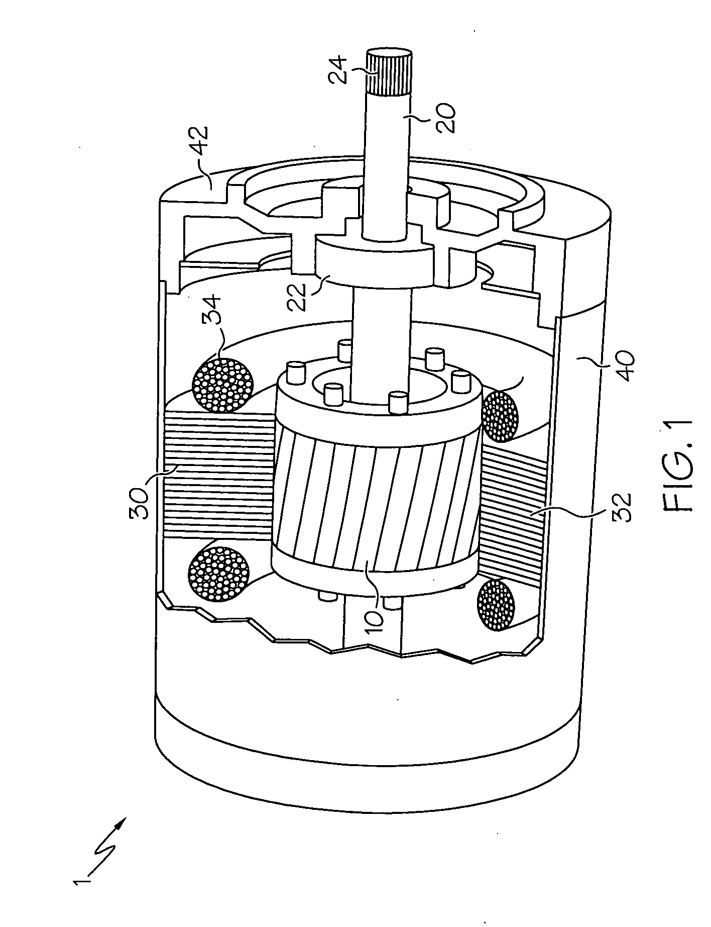
[0027]Referring initially to FIG. 1, an electric motor 1 is shown, where a rotor 10 spins in response to changes in a magnetic field from stator 30. Rotor 10 is mounted on a shaft or mandrel 20 so that the spinning motion of the rotor 10 can be turned into useful work. For example, teeth 24 formed in the end of shaft 20 can be used to interact with a complementary surface to turn a wheel, pulley, fan or the like. Motor 1, in the configuration shown where the rotor 10 and stator 30 are not in contact with one another, is referred to as an induction motor, where the principles of reciprocal induction of electric current and magnetic flux in appropriately-configured structures is well-known. A housing 40 is used to contain the rotor 10 and stator 30, while the rotatable shaft 20 may be secured to the housing 40 via one or more bearings 22 that could interact with an end plate 42 that is formed with or otherwise secured to the housing 40. As can be seen, stator 30 includes a magneticall...


PUM

PropertyMeasurementUnit
Temperatureaaaaaaaaaa

Abstract

A rotor for an induction motor and a method of preparing same. The method includes making a squirrel-cage rotor made up of a cage and a laminate stack by forming a mold around the stack, heating the stack and introducing a molten metal into the mold such that the molten metal substantially fills a space defined in the stack that corresponds to the cage. In one form, the space includes slots or related channels formed in the stack that upon filling with the molten metal become longitudinal bars that form electric current loops with end rings of the cage. By heating the stack and maintaining it at a temperature high enough to keep the molten metal in a substantially molten state at least long enough for it to flow through the slots of the stack, premature freezing of the molten metal is avoided. In addition, by providing low pressure to the molten metal in conjunction with the elevated temperature in the stack, flow is promoted to ensure a substantially porosity-free, fully dense squirrel-cage for the rotor.

Description

BACKGROUND OF THE INVENTION[0001]The present invention relates generally to electric motors and their manufacture, and more particularly, to methods for casting rotors for electric induction motors.[0002]One form of electric induction motor involves a rotating armature (rotor) surrounded by a coil-wound stationary field (stator). When electric current is passed through the stator windings, a part of the stator known as the pole (which may be made up of a magnetically permeable material, such as iron) around which the windings are wrapped becomes magnetically energized, which in turn imparts an electromagnetic force to the rotor, causing it to rotate. In motive applications, a shaft attached to the rotor can be used to provide propulsive force to a vehicle through the turning of one or more linked wheels. Such a motor could be especially useful in vehicles that rely either entirely on electric power, or as part of a hybrid system, where the electric motor and an internal combustion e...

Claims


Application Information

Patent Timeline
IPC IPC(8): H02K15/00H02K17/16
CPCH02K15/02Y10T29/49012H02K17/165
Inventor OSBORNE, MARK A.PRIEM, BARRY L.GERARD, DALE A.
Owner GM GLOBAL TECH OPERATIONS LLC
Why Eureka
Try Eureka