Mounting table structure and plasma film forming apparatus

a technology of plasma film and mounting table, which is applied in the direction of vacuum evaporation coating, coating, manufacturing tools, etc., can solve the problems of high vacuum level and clean state of processing chamber, inability to use adhesives, and inability to endure high temperatur

Active Publication Date: 2010-09-30
TOKYO ELECTRON LTD
View PDF6 Cites 38 Cited by
  • Summary
  • Abstract
  • Description
  • Claims
  • Application Information

AI Technical Summary

Benefits of technology

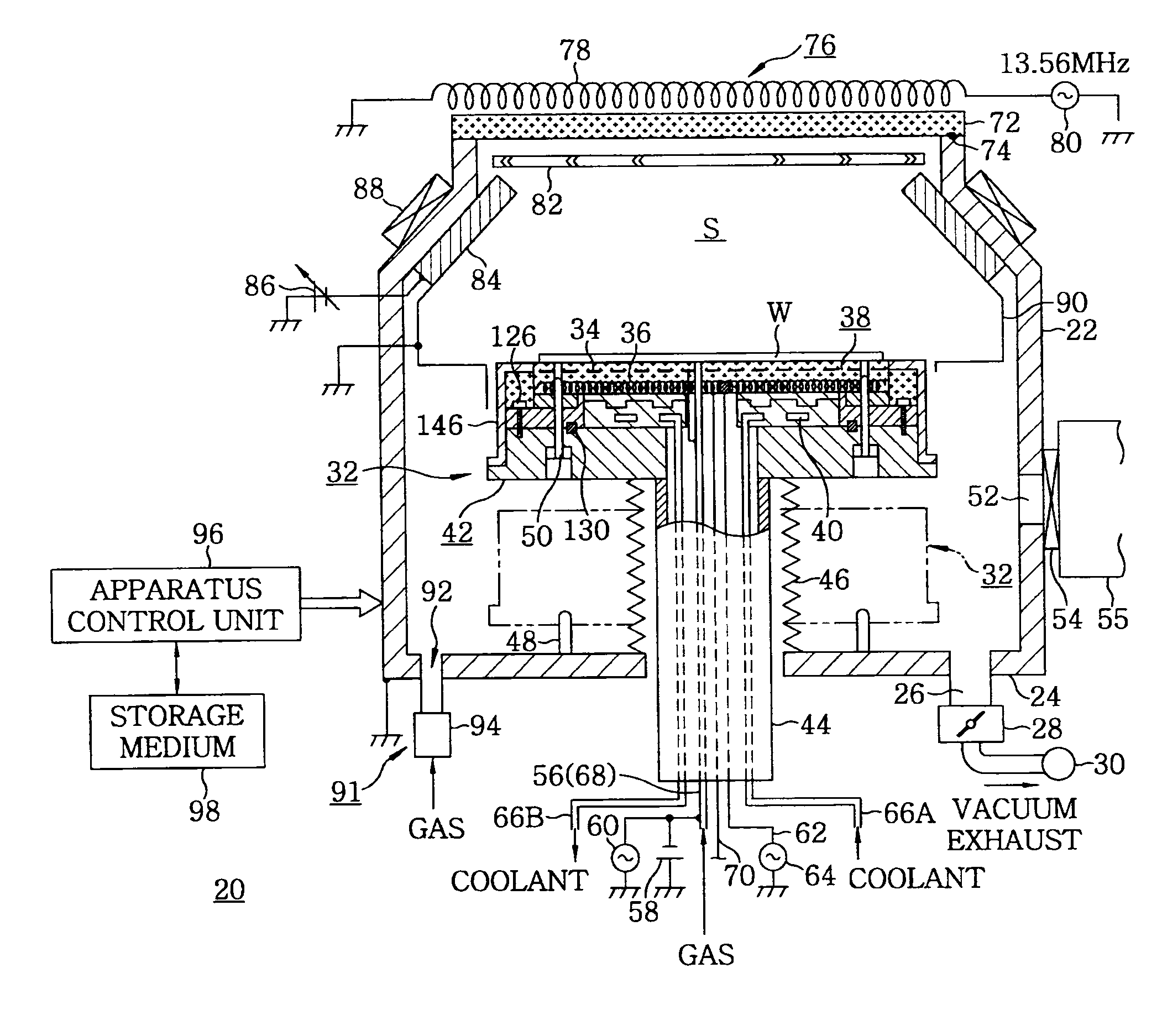
[0010]In view of the above, the present invention provides a mounting table structure capable of enduring a high temperature and a plasma film forming apparatus in which a processing chamber can be maintained at a high vacuum level by sufficiently performing a degassing treatment.

Problems solved by technology

Accordingly, it is difficult that the processing chamber is maintained at a high vacuum level and in a clean state.
Further, in order to improve the quality and characteristics of a thin film, it is required to perform a film forming process at a high process temperature of, e.g., about 400° C. However, the heat resistant temperature of the adhesive is very low, e.g., about 80° C. Thus, the adhesive cannot be used.
However, also in this case, a thermally sprayed portion has a heat resistant temperature of at most about 80° C. and, thus, cannot endure the high temperature.

Method used

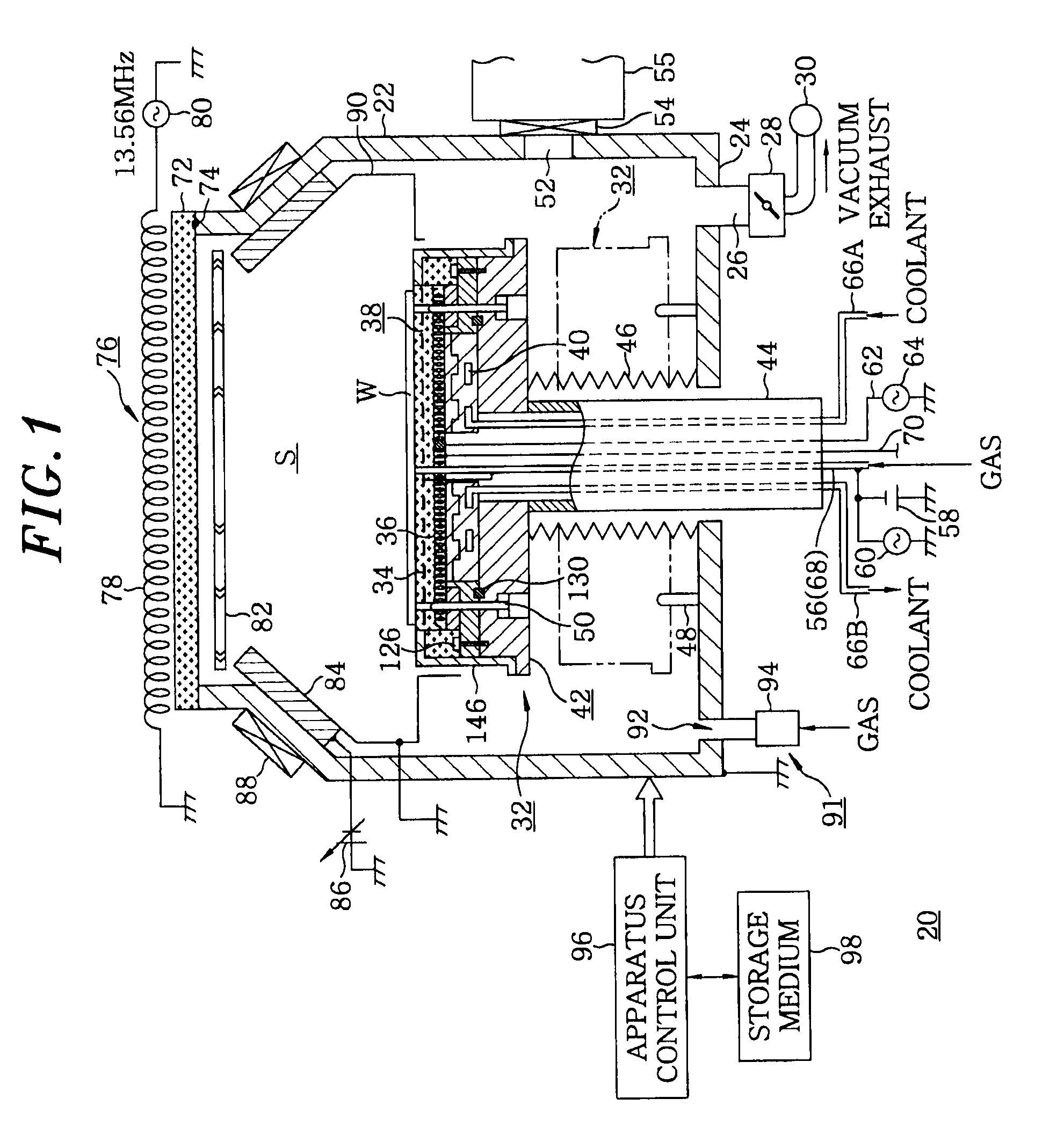

Image

  • Mounting table structure and plasma film forming apparatus
  • Mounting table structure and plasma film forming apparatus
  • Mounting table structure and plasma film forming apparatus

Examples


second embodiment

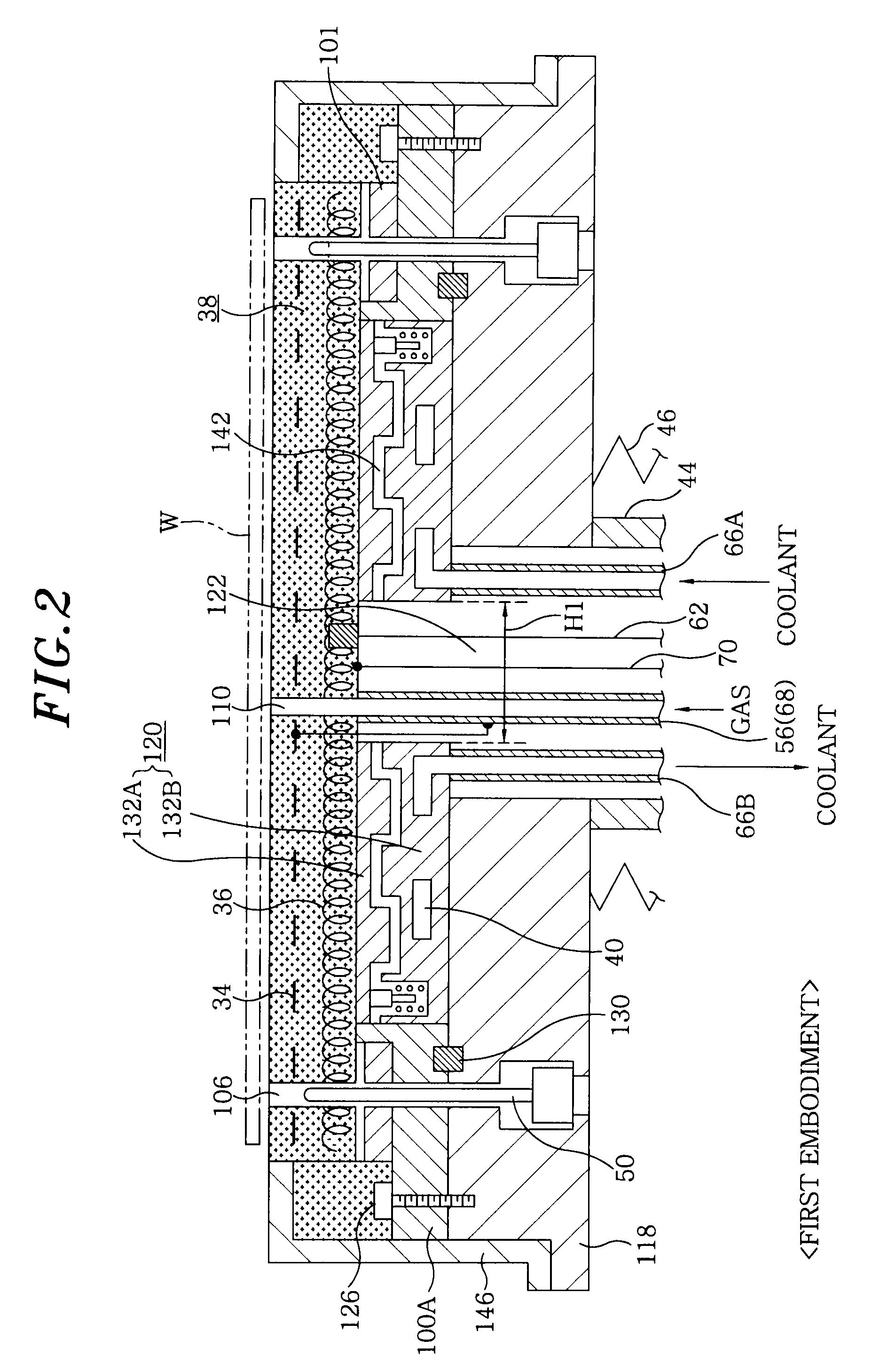
[0072]Next, a mounting table structure in accordance with a second embodiment of the present invention will be described. FIG. 7 is an enlarged cross sectional view showing essential parts of the mounting table structure in accordance with the second embodiment of the present invention. In FIG. 7, the constitutional components substantially the same as those of FIG. 2 are represented by the same reference numerals and a description thereof will be omitted.

[0073]In the first embodiment, the cooling jacket 120 is vertically divided into two parts, the upper block body 132A and the lower block body 132B, but it is not limited thereto. As shown in FIG. 7, the cooling jacket 120 may be configured as a single body without division. In this case, a small gap may be provided between the top surface of the cooling jacket 120 and the bottom surface of the mounting table 38 to horizontally form the gaseous thermal conduction buffer layer 142.

[0074]In this case, although the heat transfer area ...

third embodiment

[0075]Next, a mounting table structure in accordance with a third embodiment of the present invention will be described. FIG. 8 is an enlarged cross sectional view showing essential parts of the mounting table structure in accordance with the third embodiment of the present invention. FIG. 9 is a graph showing a relationship between a surface discharge voltage and a surface discharge distance. In FIG. 8, the constitutional components substantially the same as those of FIG. 2 are represented by the same reference numerals and a description thereof will be omitted.

[0076]In the first and second embodiments, a surface discharge may be generated along the bottom surface of the mounting table 38 at connection portions between the bottom surface of the mounting table 38 and the upper ends of the respective lines, that is, the electrode line 56 to which a DC high voltage of, e.g., 4000 V is supplied and the power supply line 62 or the thermocouple line 70 having approximately zero potential...


PUM

PropertyMeasurementUnit
heat resistant temperatureaaaaaaaaaa
temperatureaaaaaaaaaa

Abstract

A mounting table structure for mounting thereon an object to be processed to form a metal-containing thin film on the object includes a ceramic mounting table in which a chuck electrode and a heater are embedded, and a metal flange connected to a bottom surface of a peripheral portion of the mounting table. The mounting table structure further includes a metal base which is joined to the flange by screws and has a coolant path for flowing a coolant therein, and a metal seal member interposed between the flange and the base.

Description

CROSS-REFERENCE TO RELATED APPLICATIONS[0001]This application claims priority to Japanese Patent Application No. 2009-065236 filed on Mar. 17, 2009, the entire contents of which are incorporated herein by reference.FIELD OF THE INVENTION[0002]The present invention relates to a plasma film forming apparatus for forming a metal-containing thin film on an object to be processed, e.g., a semiconductor wafer, by using a plasma and a mounting table structure used therein.BACKGROUND OF THE INVENTION[0003]In general, various processes, e.g., a film forming etching process are repeatedly performed on a semiconductor wafer to manufacture semiconductor devices. With increased requirements for high-integration and high-miniaturization of semiconductor devices, a line width or hole diameter of the device is getting smaller. Further, conventionally, an aluminum alloy is widely used as a wiring material or a burying material. However, recently, there is a tendency to use tungsten (W), copper (Cu) ...

Claims


Application Information

Patent Timeline
Patent Type & Authority Applications(United States)
IPC IPC(8): B23Q3/00
CPCC23C14/50H01L21/68785H01L21/67109H01J37/34
Inventor FUJISATO, TOSHIAKINASMAN, RONALD
Owner TOKYO ELECTRON LTD
Why Eureka
Try Eureka