

Superconducting wire rod, persistent current switch, and superconducting magnet
a technology of current switch and superconducting wire, which is applied in the direction of superconducting magnet/coil, magnetic body, superconductor device, etc., can solve the problem of increasing the probability of coupling-induced superconductor quenching
- Summary
- Abstract
- Description
- Claims
- Application Information
AI Technical Summary
Benefits of technology
Problems solved by technology
Method used
Image

Examples
first embodiment
[0056]A first embodiment of the present invention will be described below by explaining about the manufacturing process of a prototype model of the persistent current switch.
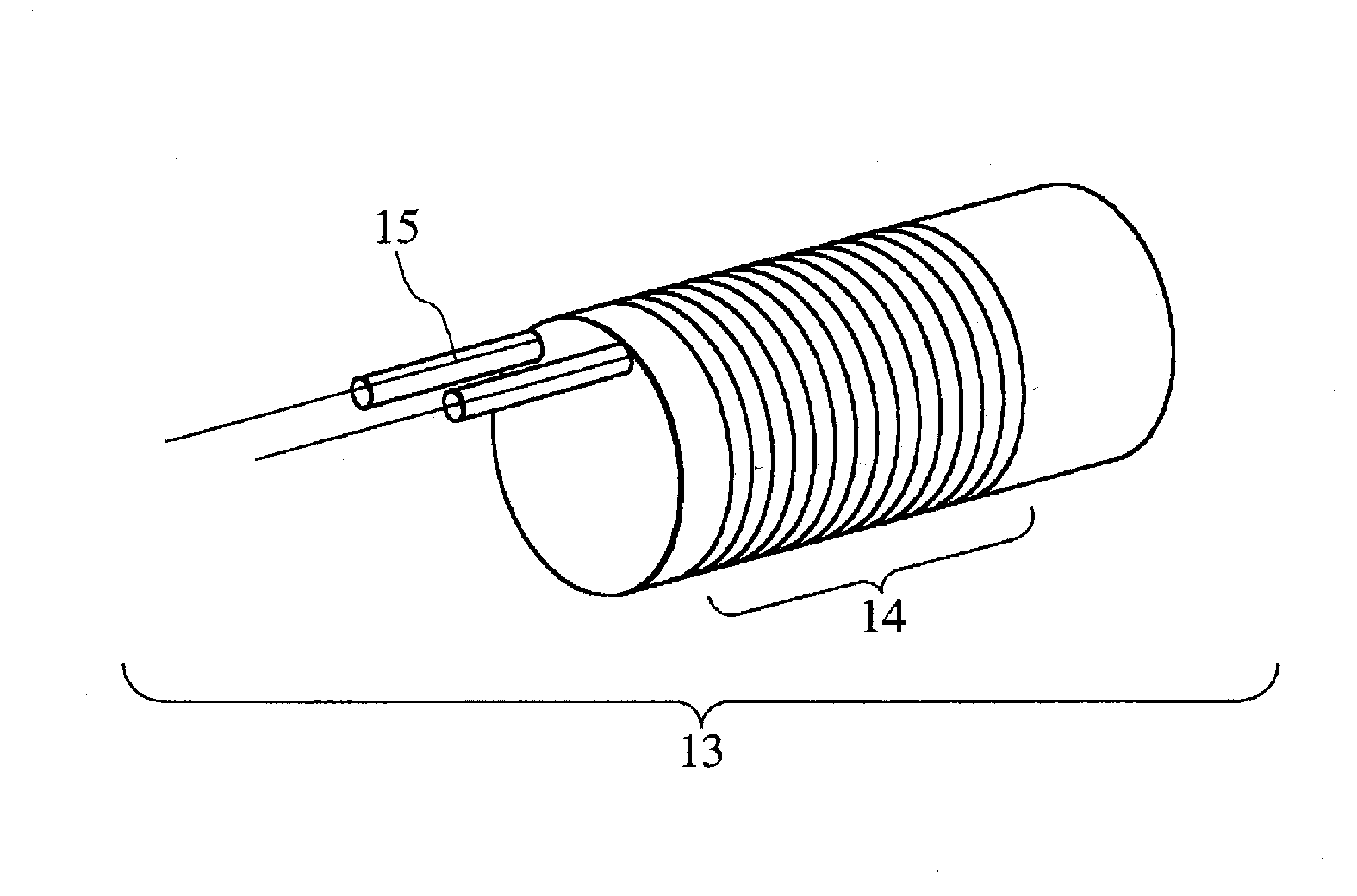
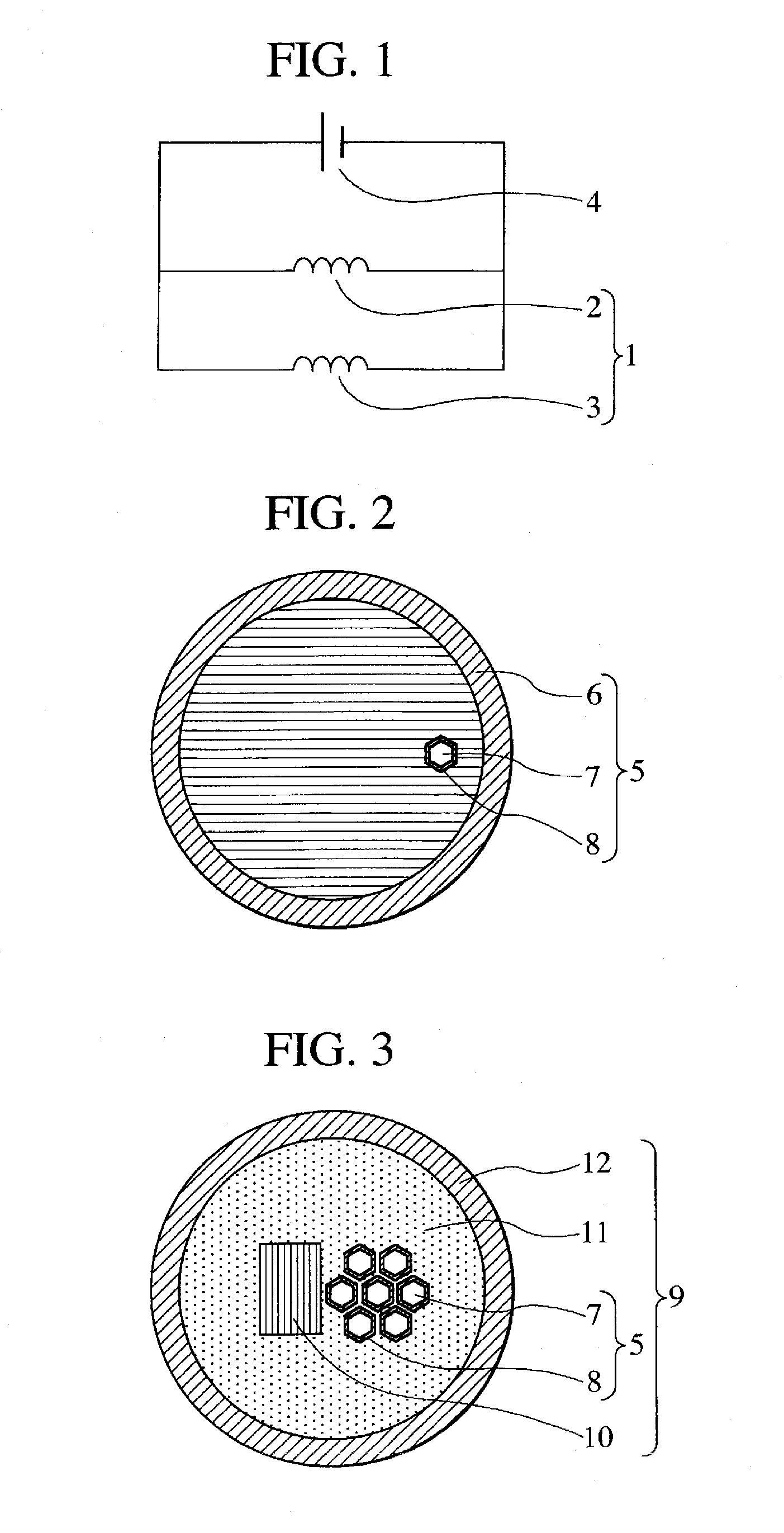
[0057]As a superconducting wire for the persistent current switch, a superconducting wire (multi-core wire having a triplex structure of CuNi—Ta—NbTi) including a normal-conducting matrix made of a Cu-10 wt % Ni alloy, a barrier layer made of Ta, and a plurality of NbTi superconducting metal filaments was used. Meanwhile a NbTi wire was used as the other superconducting wire to be connected. The persistent current switch was manufactured by using a PbBiSn alloy as a low-melting-point superconducting alloy for connection.
[0058]First of all, the superconducting wire for the persistent current switch was manufactured by performing hot extrusion and wiredrawing processes. A Ta sheet was wound around a NbTi alloy rod. The resulting assembly was sealed into a Cu-10 wt % Ni tube and subjected to hot extrusion and wired...
second embodiment
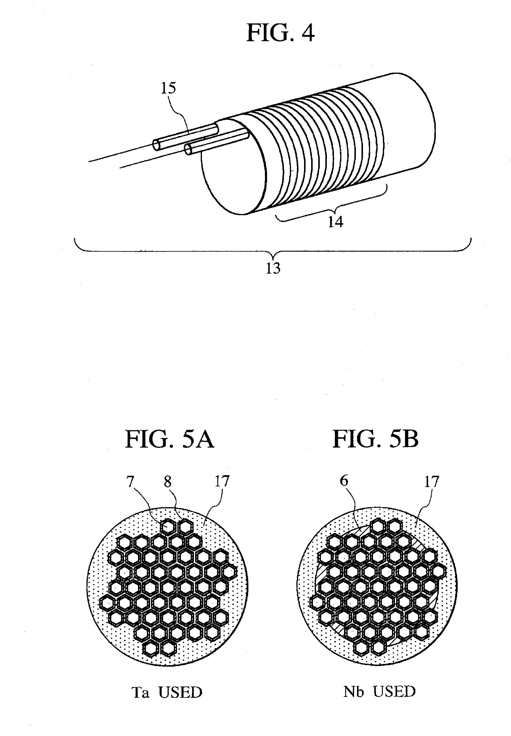
[0070]A second embodiment of the present invention will now be described. A closed-loop circuit for a persistent current test was prepared as indicated in FIG. 6. The closed-loop circuit was used to conduct a persistent current test of the persistent current switch manufactured as described in conjunction with the first embodiment. A superconducting coil 2, a persistent current switch 3, and an excitation power supply 4, which employed NbTi wires, were prepared. Superconducting connections 19 were used to connect the above-mentioned NbTi wires to connecting NbTi wires 18. Each superconducting connection was structured so that two multi-core NbTi wires were integrated and connected as shown in FIG. 5A. Ta and Mo were used as barrier materials for the NbTi wires.
[0071]The test was conducted in the sequence described below. First of all, a heater for the persistent current switch 3 was energized so that the persistent current switch switched to a normal-conducting state (9 K or higher)...
third embodiment
[0075]A third embodiment of the present invention will now be described. In the second embodiment, a superconducting coil made of a NbTi wire is used for the persistent current circuit. As regards the third embodiment, however, tests were conducted by using a superconducting coil made of a MgB2 wire, a superconducting coil made of a Nb3Sn wire, and a superconducting coil made of a Nb3Al wire.
[0076]FIG. 8 shows the result of a test that was conducted by using the superconducting coil made of a MgB2 wire. The current value used for testing purposes was 200 A. Measurements were made for 10 hours. The results of measurements indicate that no switching to a normal-conducting state took place during a persistent current operation, and that virtually no current attenuation occurred, and further that the high-value resistance of the entire closed circuit was not higher than 1×10⁻¹²Ω. In addition, the same test was conducted with the conduction current varied from 100 A to 500 A. As a result...
PUM
 Abstract
Description
Claims
Application Information