Liquid circulation unit, liquid circulation apparatus and method of manufacturing coated body

Active Publication Date: 2010-09-30
TOSHIBA TEC KK
View PDF40 Cites 15 Cited by
  • Summary
  • Abstract
  • Description
  • Claims
  • Application Information

AI Technical Summary

Benefits of technology

[0016]Accordingly, an object of the present invention is to provide a liquid circulation unit, a liquid circulation apparatus and a method of manufacturing a coated body which can exchange an ink easily, can reduce the ink used amount and can improve the operation availability.
[0020]According to the present invention, a liquid circulation unit, a liquid circulation apparatus and a method of manufacturing a coated body can be provided which can solve the conventional various problems. That is, in case of the ink changing operation, it is enough to stop the apparatus only for a time required for exchanging the detachable liquid circulation unit. In addition, it becomes possible to clean and to exchange the ink offline, and thereby the operation difficulty level can be reduced. In addition, as the pipe arrangement route is shortened, the losses of the ink and the cleaning liquid can be reduced.
[0021]In addition, as the ink does not jet under the pressurization from the nozzle side caused by the pressurization of the sub-tank, the loss of the ink is eliminated.
[0022]In addition, as the exudation and jet failure by the circulation do not occur, it is possible to jet while circulating. For the reason, the present invention has the merit that the stop time by the circulation in one time per two hours can be reduced, the operation time of the a single body of the facilities can be improved, and the line balance between the former process and the later process can be maintained.

Problems solved by technology

In such a droplet jet coating apparatus, as the ink including a material difficult to dissolve is used, the sedimentation of the material occurs by the deterioration with age of the ink, and as a result, a jet failure caused by the sedimentation is generated.
However, in the above-described droplet jet coating apparatus, as a pressure fluctuation is applied to the droplet jet head via the ink inside the pipe arrangement by driving the valve and the pump, the leakage of the ink and the suction of the air and so on occur.
For the reason, the leakage of the ink and the suction of the air bubbles by the droplet jet head occur, and as a result, a jet failure such as non-jet and so on may occur.
However, in the droplet jet coating apparatus stated in the above-described Patent Document 3, there is a problem described below.
Firstly, there is a problem that the pipe arrangement route is complicated.
In addition, the ink exchanging operation itself was very high in operation difficulty level, as it was necessary for an operator to enter into the apparatus.
In addition, as it is necessary to withdraw the ink existing in the pipe arrangement route as waste liquid, so that the losses of the ink and the cleaning liquid were high.
In addition, there is a problem that in the discharge action, while the ink in the head is sent with applied pressure by pressurizing the first buffer tank, the ink may be discharged from the nozzle side, too.
As the discharge actions are performed at a frequency of once two hours, the loss amount per day becomes very large such as 3×12=36 cc, and thus much running cost is required.
In addition, there is a problem that in the circulation action when the first buffer tank is pressurized, as the head can not coat during the circulation action, the head is to be evacuated to the evacuation position.
In addition, as the line balance between the former process and the later process can not be held, (the substrate inputted from the former process can not be treated and thus becomes a backlog) the time operation availability of the line may deteriorate.

Method used


Image

  • Liquid circulation unit, liquid circulation apparatus and method of manufacturing coated body
  • Liquid circulation unit, liquid circulation apparatus and method of manufacturing coated body
  • Liquid circulation unit, liquid circulation apparatus and method of manufacturing coated body

Examples


Embodiment Construction

[0032]Referring now to the drawings, wherein like reference numerals designate identical or corresponding parts throughout the several views, the embodiments of this invention will be described below.

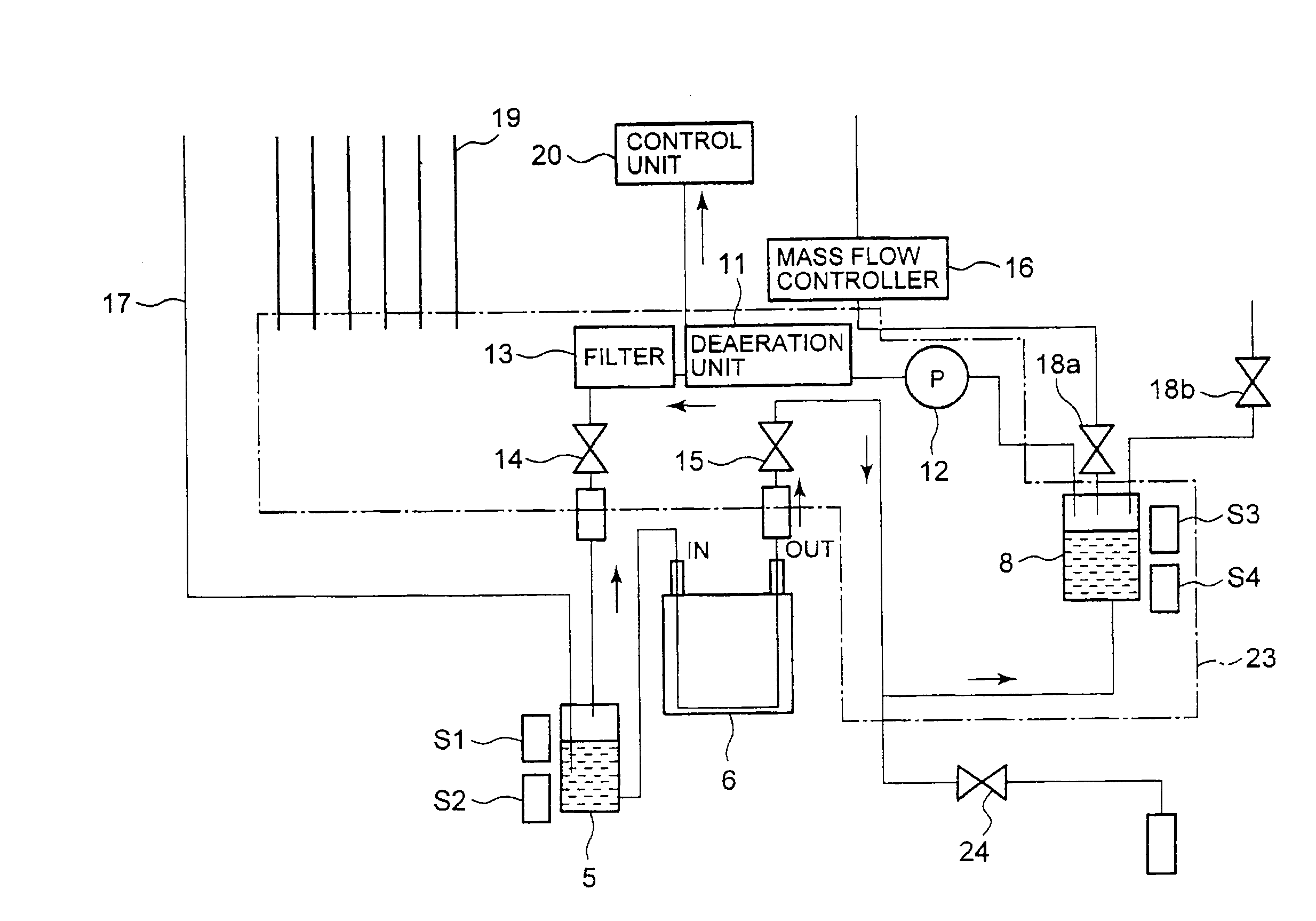
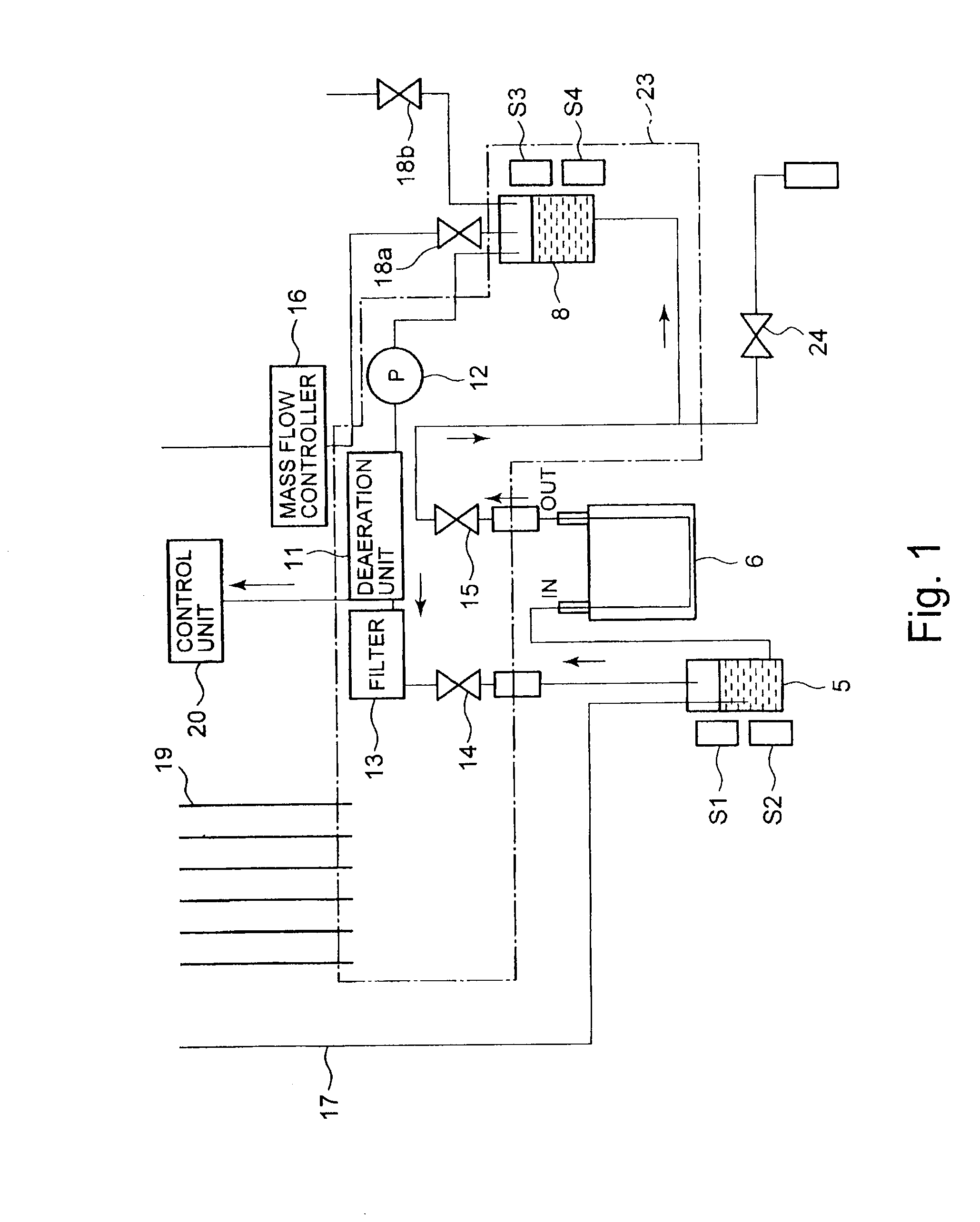
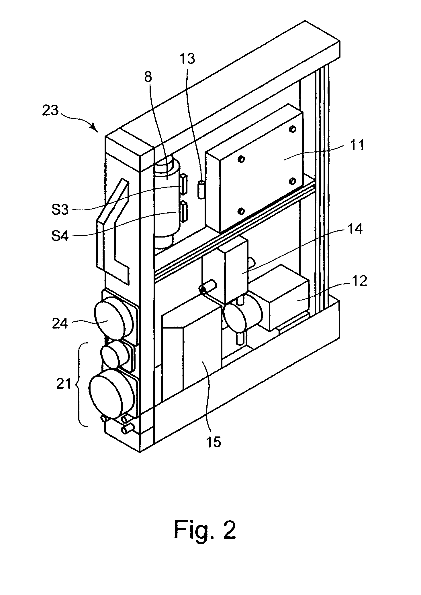
[0033]A droplet jet coating apparatus (an ink jet coating apparatus and so on) according to an embodiment of the present invention is provided with a detachable liquid circulation unit 23 in which pipe arrangement routes to circulate an ink between the head 6 and the sub-tank 5 are put together, as shown in a chained line of FIG. 1. The liquid circulation unit 23 is composed as a cartridge, and is provided with a small sized discharge tank 8, a small sized deaeration unit 11, a small sized liquid sending pump 12, a filter 13, a diaphragm valve 14, and a cock valve 15. As electric equipments such as a mass flow controller 16, a gas piping 17, a suction valve 18a, an atmosphere open valve 18b, wirings 19 and a control unit 20 for the deaeration unit 11 and so on can be used regardless of ...


PUM


Abstract

A liquid circulation unit adapted to be provided in a liquid circulation apparatus to circulate a liquid, including, a first liquid storage unit to store the liquid, a sensor to detect a fluid level of the liquid stored in the first liquid storage unit, a liquid sending pump to send the liquid to an outside from the first liquid storage unit based on a detection result of the sensor, a pipe arrangement for deaeration to remove a dissolved gas in the liquid sent from the liquid sending pump, a filter to remove an impurity in the liquid sent from the liquid sending pump, a diaphragm valve which opens when the liquid is sent to the outside from the first liquid storage unit, and a cock valve which opens when the liquid is sent to the first liquid storage unit from the outside, wherein the liquid circulation unit is adapted to be provided so as to be detachable to or from the liquid circulation apparatus.

Description

CROSS-REFERENCE TO RELATED APPLICATIONS[0001]This application is based upon and claims the benefit of priority from the prior Japanese Patent Application No. 2009-73184, filed on Mar. 25, 2009; the entire contents of which are incorporated herein by reference.BACKGROUND OF THE INVENTION[0002]1. Field of the Invention[0003]The present invention relates to a liquid circulation unit which is used for a liquid jet coating apparatus to jet and coat a droplet to an object to be coated, a liquid circulation apparatus and a method of manufacturing a coated body.[0004]2. Description of the Background[0005]A droplet jet coating apparatus is used for printing an image information, and in addition, for manufacturing various flat type display devices such as a liquid crystal display device, an organic EL (Electro Luminescence) display device, and an electron emission display device, a plasma display device, an electrophoresis display device and so on. The droplet jet coating apparatus is provide...

Claims


Application Information

Patent Timeline
IPC IPC(8): B41J29/38B41J2/175B05D5/00
CPCB41J2/175B41J2/17513B41J2/1752B41J2/18B41J2/17563B41J2/17566B41J2/17596B41J2/17553
Inventor OOISHI, YASUSHIISHIHARA, HARUHIKOOOSHIRO, KENICHI
Owner TOSHIBA TEC KK
Why Eureka
Try Eureka