Clock generation in MRI receivers

a clock generation and receiver technology, applied in the direction of amplitude demodulation, instruments, code conversion, etc., can solve the problems of even more severe problems, one of the most complex and challenging aspects of cost effective design and production of mr scanners

Active Publication Date: 2010-10-14
KONINKLIJKE PHILIPS ELECTRONICS NV
View PDF10 Cites 21 Cited by
  • Summary
  • Abstract
  • Description
  • Claims
  • Application Information

AI Technical Summary

Benefits of technology

[0016]In accordance with an embodiment of the invention, the first clock generator and the third clock generator form a feedback loop, wherein the first clock generator is controlled by the feedback loop. Alternatively, the second clock generator can also be comprised in the feedback loop. Using the feedback loop has the advantage, that both sampling clock and system clock are in constant frequency lock with respect to the central timing reference and hence all (remote) MRI receivers in the system operate in a synchronous fashion, allowing central real time (software) control of all receivers.
[0017]In accordance with an embodiment of the invention, the feedback loop is a phase locked loop. In all embodiments, by having the VCXO based sampling clock as the direct clock source for the ADC sampling process, any circuit which could possibly add phase noise to the sampling clock is eliminated.

Problems solved by technology

All these components are typically strewn over a distance of 10-20 meters between the receive chain in the exam room and the analogue to digital converters in a technical room, which makes it one of the most complex and challenging aspects to cost effectively design and produce an MR scanner due to component spread and unwanted interactions between the many galvanic parts.
These problems become even more severe in the case of higher element counts in coils, i.e. coil systems comprising multiple individual coils which need to be effectively combined using a state of the art wire technology.

Method used


Image

  • Clock generation in MRI receivers
  • Clock generation in MRI receivers
  • Clock generation in MRI receivers

Examples


Embodiment Construction

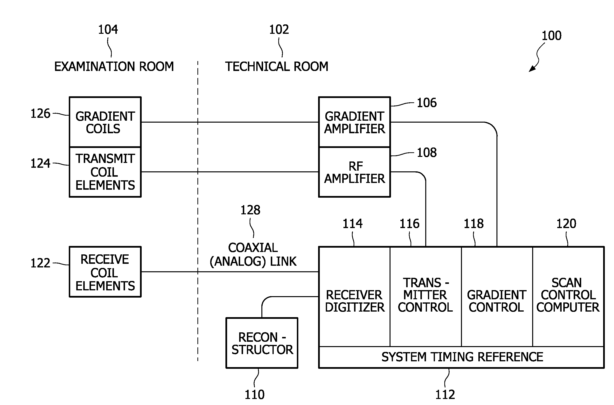
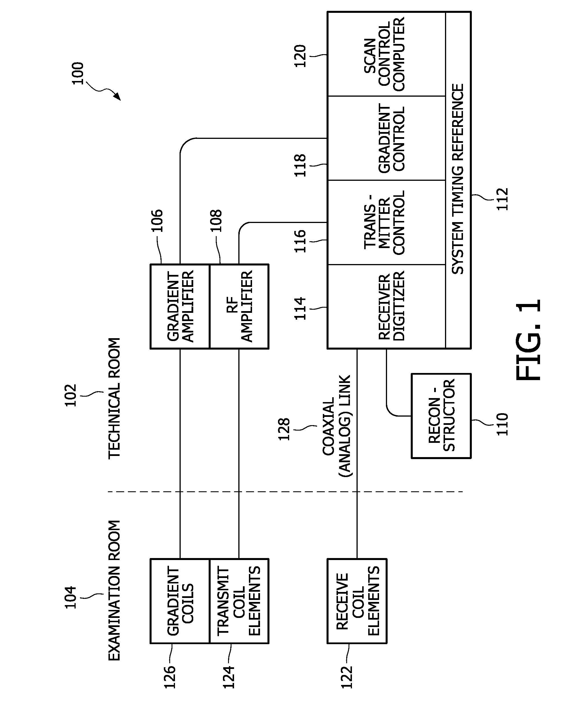
[0037]FIG. 1 illustrates a state of the art MRI system 100. The state of the art system is separated into two parts, the electrical components which are located in the examination room 104 and the electrical components which are located in the technical room 102. The reason for that separation is, that in the examination room the MRI magnet is located together with its gradient coils 126, its transmit coil elements 124 and the receive coil elements 122. For excitation of nuclei for MR imaging purposes, high frequency RF pulses have to be applied via the transmit coil elements 124 and detected by the receive coil elements 122. The shielding of the examination room ensures that a high quality reception of RF signals without strong disturbances is possible. This also requires a galvanic separation of the electrical components located in the examination room and the electrical components located in the technical room 102.

[0038]In the technical room, a gradient amplifier 106 and an RF am...


PUM


Abstract

The invention relates to a nuclear magnetic resonance imaging radio frequency receiver, the receiver being adapted to receive analogue signals from at least one radio frequency receiver coil unit (122; 204; 306), the radio frequency receiver comprising an analogue-digital converter (408) to convert the analogue magnetic resonance signal into a first digital signal, a resampling and demodulation unit (414) to convert the first digital signal into a second digital signal, a communication interface (400: 600; 602) adapted for transmitting the second digital signal via a communication link (202), and a first clock generator (406) for generating a sampling clock, the sampling clock being the direct clock source for the analogue-digital converter (408), the first clock generator (406) being adapted to generate the sampling clock using a digital timing reference, the digital timing reference being received digitally via the communication link (202) by the communication interface (400: 600; 602), wherein the receiver further comprises a second clock generator (410) for generating a system clock, the system clock being the direct clock source for the resampling and demodulation unit (414), the second clock generator (410) being adapted to generate the system clock using the sampling clock.

Description

TECHNICAL FIELD[0001]The invention relates to a nuclear magnetic resonance imaging radio frequency receiver, a method of receiving a radio frequency signal from a magnetic resonance imaging receiver coil unit and a computer program product.BACKGROUND AND RELATED ART[0002]Magnetic resonance imaging (MRI) is a state of the art imaging technology which allows cross sectional viewing of objects like a human body with unprecedented tissue contrast. MRI is based on the principles of nuclear magnetic resonance (NMR), a spectroscopic technique used by scientists to obtain microscopic chemical and physical information about molecules. The basis of both NMR and MRI is the fact, that atomic nuclei with non-zero spin have a magnetic moment. In medical imaging it is usually nuclei of hydrogen atoms (i.e. protons 1H) which are studied since they are present in the body in high concentrations like for example as water. Radio frequency waves are directed at the nuclei in strong external magnetic fi...

Claims


Application Information

Patent Timeline
Patent Type & Authority Applications(United States)
IPC IPC(8): H04L27/06
CPCG01R33/3621H03M1/1245G01R33/3692
Inventor ROEVEN, HENRICUS GERARDUS
Owner KONINKLIJKE PHILIPS ELECTRONICS NV
Why Eureka
Try Eureka