Multi-beam active phased array architecture

a phased array and active technology, applied in the field of multi-beam active phased array architecture, can solve the problems of increasing the cost and complexity of the architecture, increasing the cost of commercial applications, and increasing the cost of switching delay lines, so as to improve system capacity and flexibility, optimize system availability, and increase capacity and availability

Active Publication Date: 2010-10-14
VIASAT INC
View PDF42 Cites 75 Cited by
  • Summary
  • Abstract
  • Description
  • Claims
  • Application Information

AI Technical Summary

Benefits of technology

[0020]Advantages of the exemplary phased array antenna include increased system capacity and flexibility. Furthermore, an antenna that can operate over multiple frequency bands optimizes system availability. This system may be

Problems solved by technology

The main drawback of fully electronic steering is that the antenna usually requires the integration of a lot of expensive analog RF electronic components which may prohibitively raise the cost for commercial applications.
Additionally, a typical electronically steerable phased array requires at least a few of these components at every element in the phased array, which increases the cost and complexity of the architecture.
Another typical digital phase shifter implements a switched high-pass low-pass filter architecture which has better operating bandwidth compared to a switched delay line but is still physically large.
However, in addition to being a higher quality material than the other possible materials, GaAs is also more expensive and more difficult to manufacture.
The typical phased array components take up a lot of area on the GaAs, and result in higher costs.
Furthermore, a standard phase shifter has high RF loss, which is typically about n+1 dB of loss, where n is the number of phase bits in the phase shifter.
Another prior art embodiment uses RF MEMS switches and has lower loss but still consumes similar space and is generally incompatible with monolithic solutions.
In general, quadrature hybrids and 180° hybrids are limited in frequency band and require significant physical space.
Moreover, the quadrature hybrids and 180° hybrids are typically made of GaAs and have associated RF power loss on the order of 3-4 dB per hybrid when us

Method used


Image

  • Multi-beam active phased array architecture
  • Multi-beam active phased array architecture
  • Multi-beam active phased array architecture

Examples


Embodiment Construction

[0051]While exemplary embodiments are described herein in sufficient detail to enable those skilled in the art to practice the invention, it should be understood that other embodiments may be realized and that logical material, electrical, and mechanical changes may be made without departing from the spirit and scope of the invention. Thus, the following detailed description is presented for purposes of illustration only.

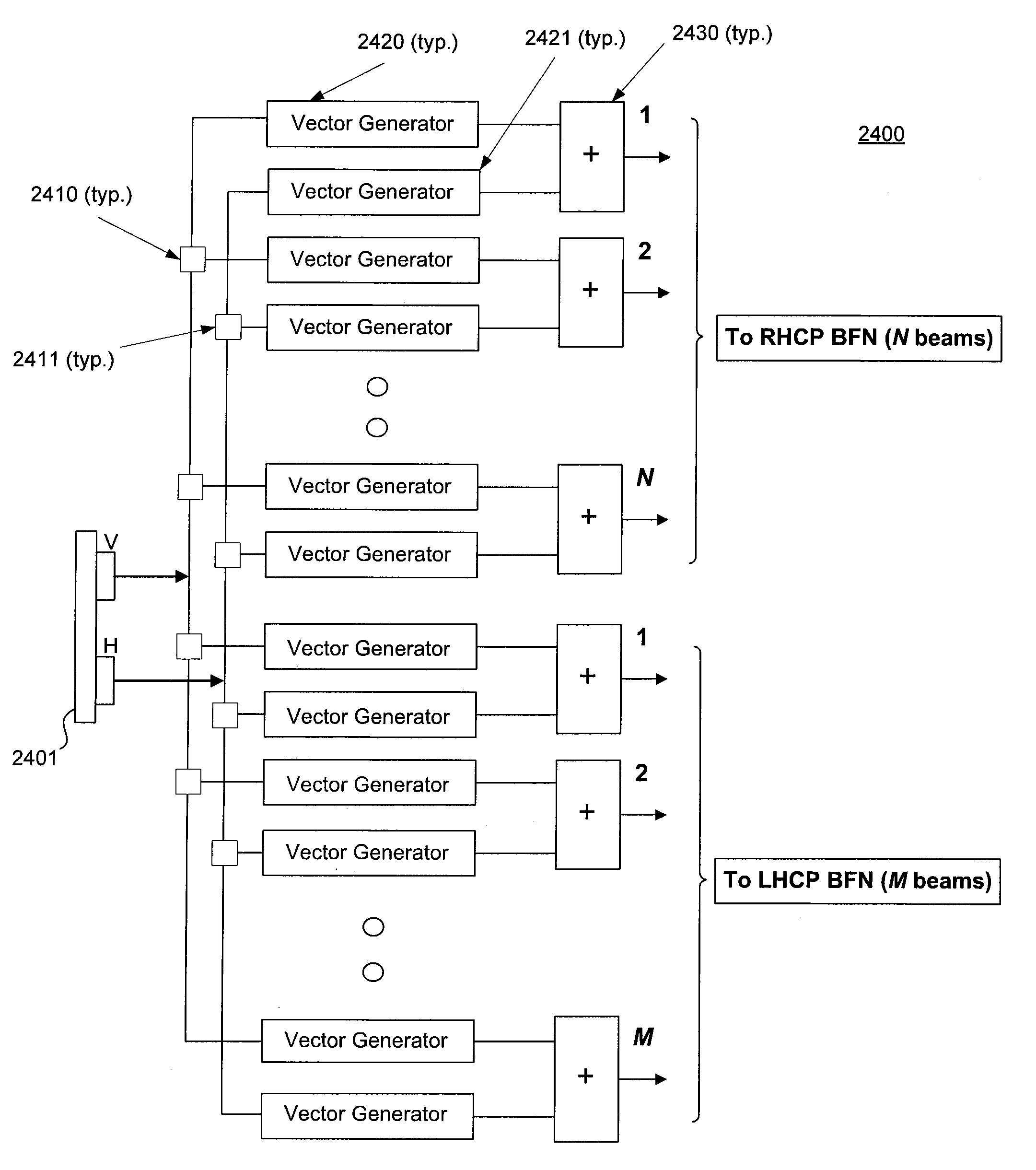
[0052]An electronically steerable phased array antenna may be used in various scenarios. For example, the phased array antenna may be implemented in COTM antennas, SATCOM airborne terminals, SATCOM mobile communications, and SATCOM earth terminals. In an exemplary embodiment, a phased array antenna comprises a layout of various active component building blocks, such as baluns, power splitters, power combiners, hybrids, and vector generators. Although throughout the application reference may be made to “active power splitters, vector generators, and active power comb...


PUM


Abstract

In an exemplary embodiment, a phased array antenna comprises multiple subcircuits in communication with multiple radiating elements. The radio frequency signals are adjusted for both polarization control and beam steering. In a receive embodiment, multiple RF signals are received and combined into at least one receive beam output. In a transmit embodiment, at least one transmit beam input is divided and transmitted through multiple radiating elements. In an exemplary embodiment, the phased array antenna provides multi-beam formation over multiple operating frequency bands. The wideband nature of the active components allows for operation over multiple frequency bands simultaneously. Furthermore, the antenna polarization may be static or dynamically controlled at the subarray or radiating element level.

Description

CROSS REFERENCE TO RELATED APPLICATIONS[0001]This application is a non-provisional of U.S. Provisional Application No. 61 / 237,967, entitled “ACTIVE BUTLER AND BLASS MATRICES,” which was filed on Aug. 28, 2009. This application is also a non-provisional of U.S. Provisional Application No. 61 / 259,375, entitled “ACTIVE HYBRIDS FOR ANTENNA SYSTEMS,” which was filed on Nov. 9, 2009. This application is a non-provisional of U.S. Provisional Application No. 61 / 234,513, entitled “ACTIVE FEED FORWARD AMPLIFIER,” which was filed on Aug. 17, 2009. This application is a non-provisional of U.S. Provisional Application No. 61 / 222,354, entitled “ACTIVE PHASED ARRAY ARCHITECTURE,” which was filed on Jul. 1, 2009. This application is a non-provisional of U.S. Provisional Application No. 61 / 168,913, entitled “ACTIVE COMPONENT PHASED ARRAY ANTENNA,” which was filed on Apr. 13, 2009. This application is also a non-provisional of U.S. Provisional Application No. 61 / 259,049, entitled “DYNAMIC REAL-TIME P...

Claims


Application Information

Patent Timeline
IPC IPC(8): H04B1/04H01Q19/00H04B1/16
CPCH01Q3/26H01Q3/36H01Q3/34G06G7/12H01Q15/242H03H11/36
Inventor CORMAN, DAVID W.ZIENKEWICZ, ROBSAUNDERS, DAVID R.
Owner VIASAT INC
Why Eureka
Try Eureka