Conjugated icp and ecr plasma sources for wide ribbon ion beam generation and control

a plasma source and ribbon ion beam technology, which is applied in the field of conjugated icp and ecr plasma sources for wide ribbon ion beam generation and control, can solve the problems of non-uniform plasma density profile, non-uniform plasma radial distribution, and inability to perform thin implants, so as to improve the uniformity of extracted ion beams

Active Publication Date: 2010-10-21
VARIAN SEMICON EQUIP ASSOC INC
View PDF6 Cites 10 Cited by
  • Summary
  • Abstract
  • Description
  • Claims
  • Application Information

AI Technical Summary

Benefits of technology

[0012]In a further embodiment, a multicusp magnetic field surrounding the diffusion chamber is used to further improve the uniformity of the extracted ion beam.

Problems solved by technology

While these quasithermal plasma sources are effective in generating the desired ion densities, they are typically only used to create atomic ions, due to the high temperatures developed within the arc chamber.
However, due to their heavier mass, shallow implants can be performed.
The microwaves may heat free electrons in the gas which in turn collide with the atoms or molecules of the gas in the volume and cause ionization.
The drawback for this geometry is that the plasma is radially non-uniform, i.e., the plasma column has a very peaked density profile on the axis of the discharge.
This non-uniform plasma density profile along radial direction characteristic limits the application of this geometry for large area plasma processing.
However, although smoother, for some applications, the density profile is unacceptable because it still tracks the plasma density profile in the source, as seen in FIG. 2.

Method used


Image

  • Conjugated icp and ecr plasma sources for wide ribbon ion beam generation and control
  • Conjugated icp and ecr plasma sources for wide ribbon ion beam generation and control
  • Conjugated icp and ecr plasma sources for wide ribbon ion beam generation and control

Examples


first embodiment

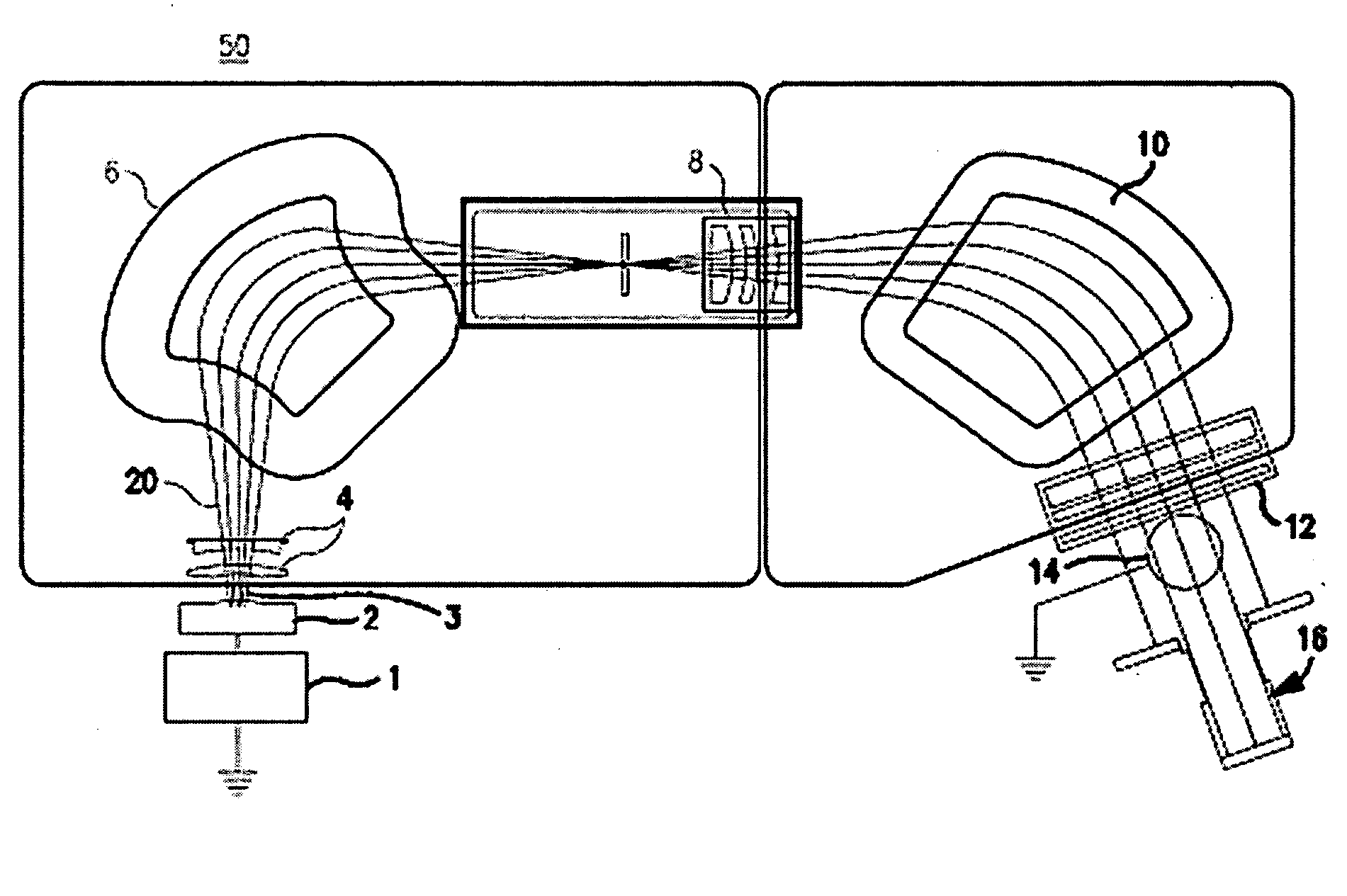
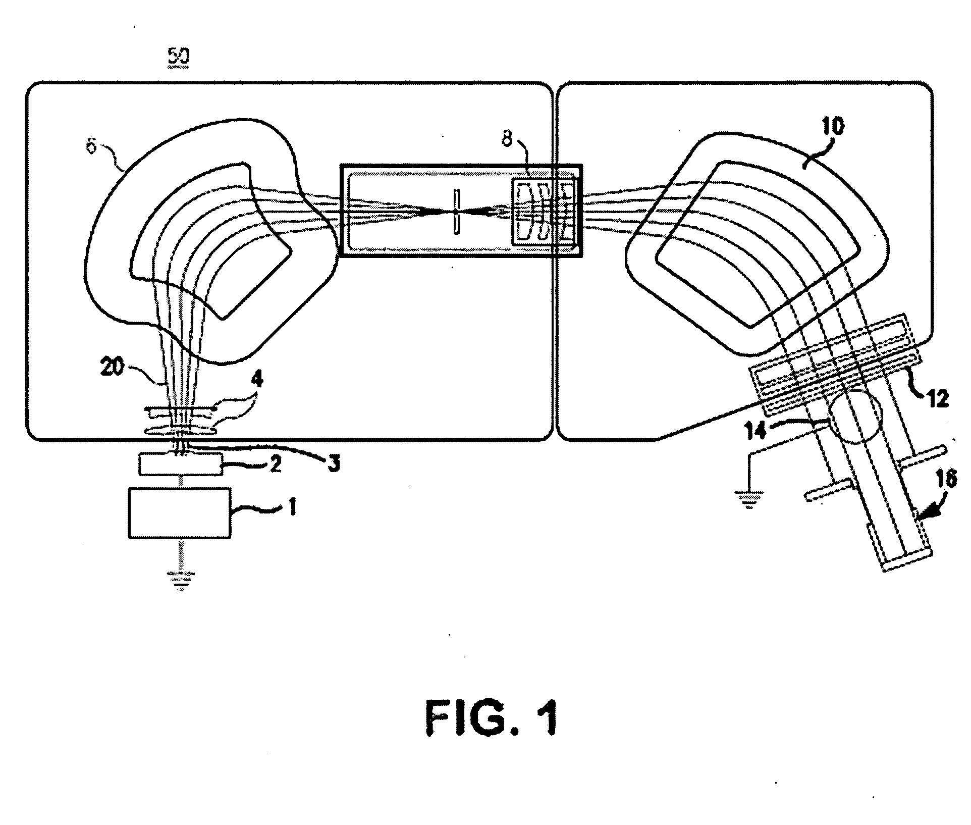
[0037]FIG. 5a illustrates the ion source 300. Two ICP plasma sources 301, 302 such as those described in conjunction with FIG. 3, are axially mated with a diffusion chamber 210. The diffusion chamber 210 is preferably in the shape of a cylinder, preferably having a diameter greater than that of the dielectric cylinders 301,302 such as 20-50 cm. The ICP sources and the diffusion chamber are aligned such that the central axes are collinear; in other words the three components are coaxial. The extraction aperture 330 is located on the diffusion chamber 210, parallel to the central axis of the chamber. The height of the extraction aperture is preferably small, such as 3-5 mm. The length of the diffusion chamber 210 can be chosen to accommodate ribbon ion beam extraction slit 330 having width of 35 cm, which will allow implantation of 300 mm diameter wafers. Because there are not limiting conditions on the length of the diffusion chamber, a wider extraction aperture of 50 cm that would p...

second embodiment

[0038]FIG. 5b illustrates the plasma ion source 300. Instead of conjugated ICP sources, two ECR plasma sources 301, 302 such as those described in conjunction with FIG. 4, are axially mated with a diffusion chamber 210.

[0039]FIG. 6a shows a side view of a representative diffusion chamber, while FIG. 6b shows a cross-section of a representative diffusion chamber that can be used with the embodiments shown in FIGS. 5a-b. As shown in FIG. 6b, the chamber housing 240 of the diffusion chamber 210 is preferably constructed of aluminum or a similar magnetically permeable material. In certain embodiments, an electrically conductive liner 245 is placed around the inner surface of the chamber housing. This liner 245, which is preferably made of doped silicon carbide or graphite, has two purposes. First, it serves to reduce sputtering and possible contamination of the plasma 260 and resulting ion beam 270 with metals from the chamber wall 240. Second, its electrical conductive nature ensures a...


PUM


Abstract

An ion source, capable of generating high-density wide ribbon ion beam, utilizing one or more plasma sources is disclosed. In addition to the plasma source(s), the ion source also includes a diffusion chamber. The diffusion chamber has an extraction aperture oriented along the same axis as the dielectric cylinder of the plasma source. In one embodiment, dual plasma sources, located on opposing ends of the diffusion chamber are used to create a more uniform extracted ion beam. In a further embodiment, a multicusp magnetic field is used to further improve the uniformity of the extracted ion beam.

Description

BACKGROUND OF THE INVENTION[0001]Ion implanters are commonly used in the production of integrated circuits (IC) to create in a semiconductor wafer, usually silicon, regions of different conductivity by p- or n-type doping. In such devices, a plasma source is used to ionize the dopant gas. A beam of positive ions is extracted from the source, accelerated to the desired energy, mass filtered and then directed toward the wafer. As the ions strike the wafer, they penetrate to a certain depth (depending on their kinetic energy and mass) and create regions of different electrical conductivity (depending on the dopant element concentration) into the wafer. The n- or p-doping nature of these regions, along with their geometrical configuration on the wafer, define their functionality, e.g., n-p-n or p-n-p junctions within the transistors. Through interconnection of many such doped regions, the wafers can be transformed into complex integrated circuits.[0002]A block diagram of a representativ...

Claims


Application Information

Patent Timeline
Patent Type & Authority Applications(United States)
IPC IPC(8): H01J27/00
CPCH01J37/08H01J37/3171H01J2237/061H01L31/206H01J2237/0815H01L31/0288H01L31/1804H01J2237/065Y02P70/50
Inventor BILOIU, COSTELSCHEUER, JAYPEREL, ALEXANDER
Owner VARIAN SEMICON EQUIP ASSOC INC
Why Eureka
Try Eureka