
Method and apparatus for microlens array/fiber optic imaging

a technology of fiber optic imaging and microlens array, which is applied in the direction of optical radiation measurement, luminescent dosimeters, instruments, etc., can solve the problems of large spectral coverage, small free spectral range of interference filters, and distinct limitations

Active Publication Date: 2010-10-21
CHEMIMAGE TECH LLC
View PDF13 Cites 18 Cited by
  • Summary
  • Abstract
  • Description
  • Claims
  • Application Information

AI Technical Summary

Benefits of technology

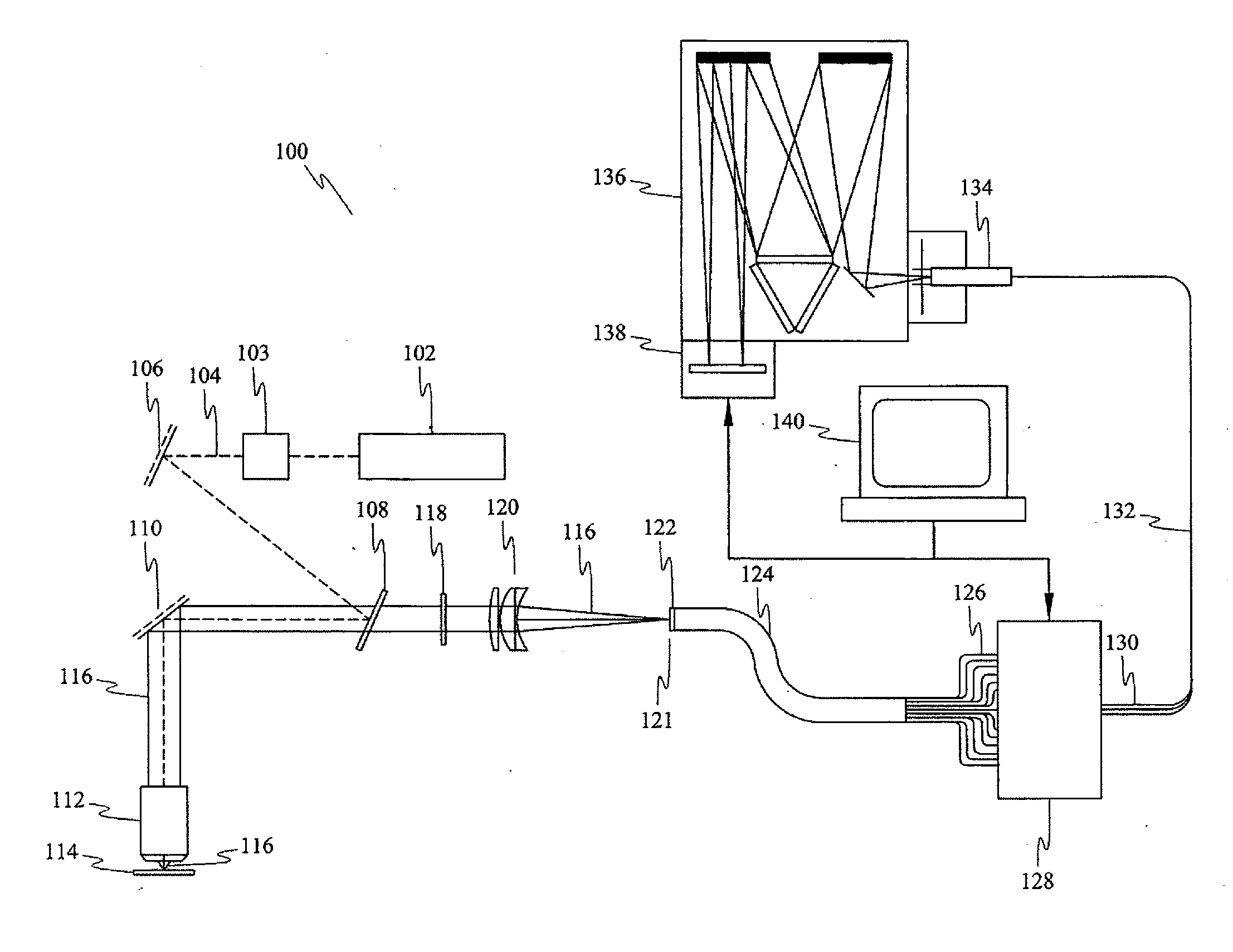
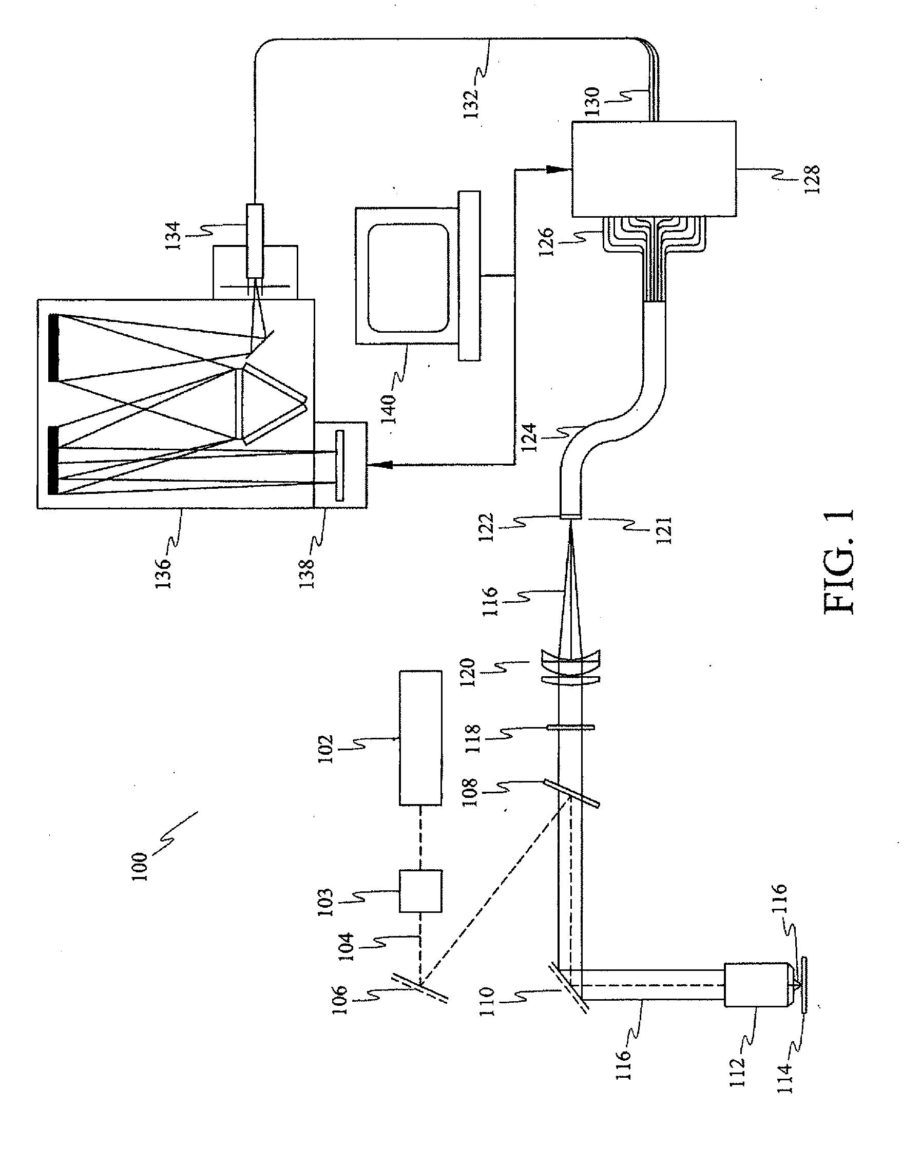
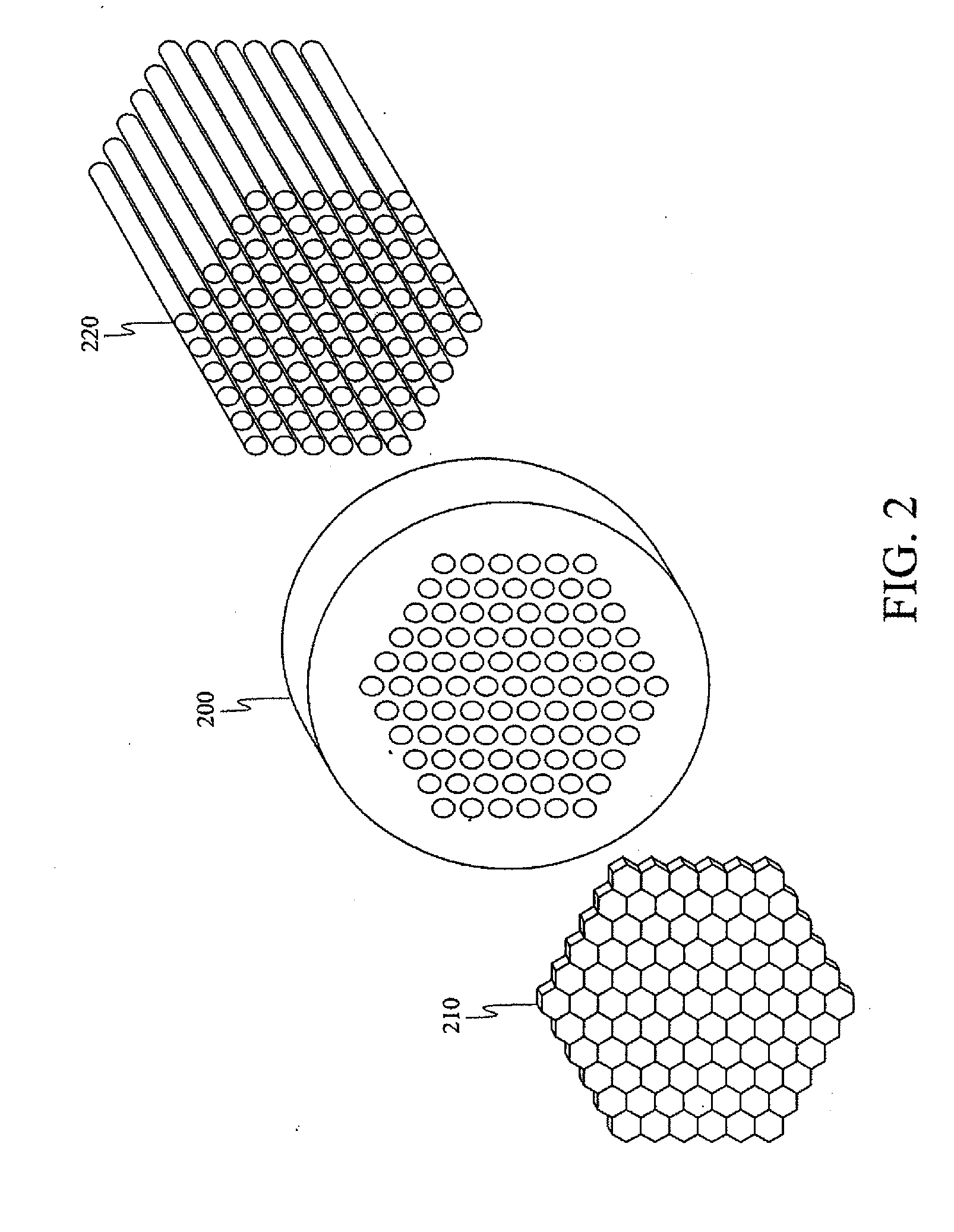
The patent describes a system and method for producing a spatially accurate wavelength-resolved image of a sample using optical fibers and a charge coupled device. The system includes a first optical fiber bundle with M fibers, a second optical fiber bundle with N fibers, an optical switch, and a control system to control the charge coupled device. The method involves illuminating the sample with photons, collecting the scattered photons, and transmitting them to the charge coupled device. The system and method can produce images with high accuracy and without the need for an optical filter. Additionally, the patent describes a method for polarization-independent imaging and a method for forming a Raman image from a sample.

Problems solved by technology

Because the wavelength selection is a function of the beam's incident angle, there are at least two inherent disadvantages to using a tunable filter.
First, interference filters have a small free spectral range.
An AOTF Raman imaging system can provide high throughput and broad spectral coverage but it has distinct limitations.
For example, such filters suffer from broad spectral bandpass which considerably degrades imaging performance from the diffraction-limited conditions.
In addition, LCTFs are susceptible to thermally-induced drift in their spectral bandpass.
Finally, LCTF systems are costly.

Method used


Image

  • Method and apparatus for microlens array/fiber optic imaging
  • Method and apparatus for microlens array/fiber optic imaging
  • Method and apparatus for microlens array/fiber optic imaging

Examples


Embodiment Construction

[0029]As stated, in Raman spectroscopy, laser light induces a scattering effect on the sample. Chemical composition and structure are determined by the light emitted from the sample. Typical data output includes intensity values at wavelengths in a predefined range. In Raman chemical imaging, Raman spectroscopy is combined with imaging processes. Light intensity is recorded as a function of both wavelength and location. The image domain contains the full image at each individual wavelength. The spectroscopy domain contains the fully resolved spectrum at each individual pixel. As a result of Raman chemical imaging, both structural and compositional information can be determined consistently.

[0030]The embodiments disclosed herein provide novel method and apparatus particularly suitable for analytical chemistry, biotechnology, material science, medical science and pharmaceuticals. The embodiments disclosed herein retain the advantageous features of both non-imaging Raman spectroscopy a...


PUM

PropertyMeasurementUnit
wavelengthsaaaaaaaaaa
diameteraaaaaaaaaa
wavelengthaaaaaaaaaa

Abstract

A novel approach for chemical imaging is disclosed. In one embodiment, the disclosure relates to a system for producing a spatially accurate wavelength-resolved image of a sample from photons scattered from the sample, comprising an optical lens; a first optical fiber bundle of M fibers; a second optical fiber bundle of N fibers; an optical fiber switch; and a charge coupled device, wherein the image comprises plural sub-images, and wherein each sub-image is formed from photons scattered from a predetermined two spatial dimension portion of the sample, and wherein the scattered photons forming each sub-image have a predetermined wavelength different from a predetermined wavelength of scattered photons forming the other sub-images, and wherein the scattered photons for each sub-image are collected substantially simultaneously.

Description

[0001]This application claims the filing date benefit of U.S. Provisional Application No. 60 / 583,840, filed Jun. 30, 2004, the specification of which is incorporated herein in its entirety.BACKGROUND[0002]Chemical imaging has a powerful capability for material characterization, process monitoring, quality control and disease-state determination. Chemical imaging combines chemical analysis with high-resolution optical imaging including optical spectroscopy, Raman imaging as well as fluorescent and IR techniques.[0003]Raman effect is a phenomenon in which a specimen scatters incident light of a given frequency into a spectrum which has lines caused by interaction of the incident light with the molecules making up the specimen. Different molecular species have different characteristic Raman spectra. Consequently, the Raman effect can be used to analyze the molecular species present in the sample. Raman chemical imaging provides molecular-specific image contrast without the use of strai...

Claims


Application Information

Patent Timeline
Patent Type & Authority Applications(United States)
IPC IPC(8): G01J3/44G01J1/58G01N21/55H01L27/00
CPCG01J3/02G01J3/0218G02B6/06G01J3/2823G01J3/44G01J3/0221
Inventor ZHANG, JINGYUN
Owner CHEMIMAGE TECH LLC
Learn More