
Syphon Filtration System

Inactive Publication Date: 2010-10-28
KORZENIOWSKI JAN A
View PDF17 Cites 9 Cited by
  • Summary
  • Abstract
  • Description
  • Claims
  • Application Information

AI Technical Summary

Benefits of technology

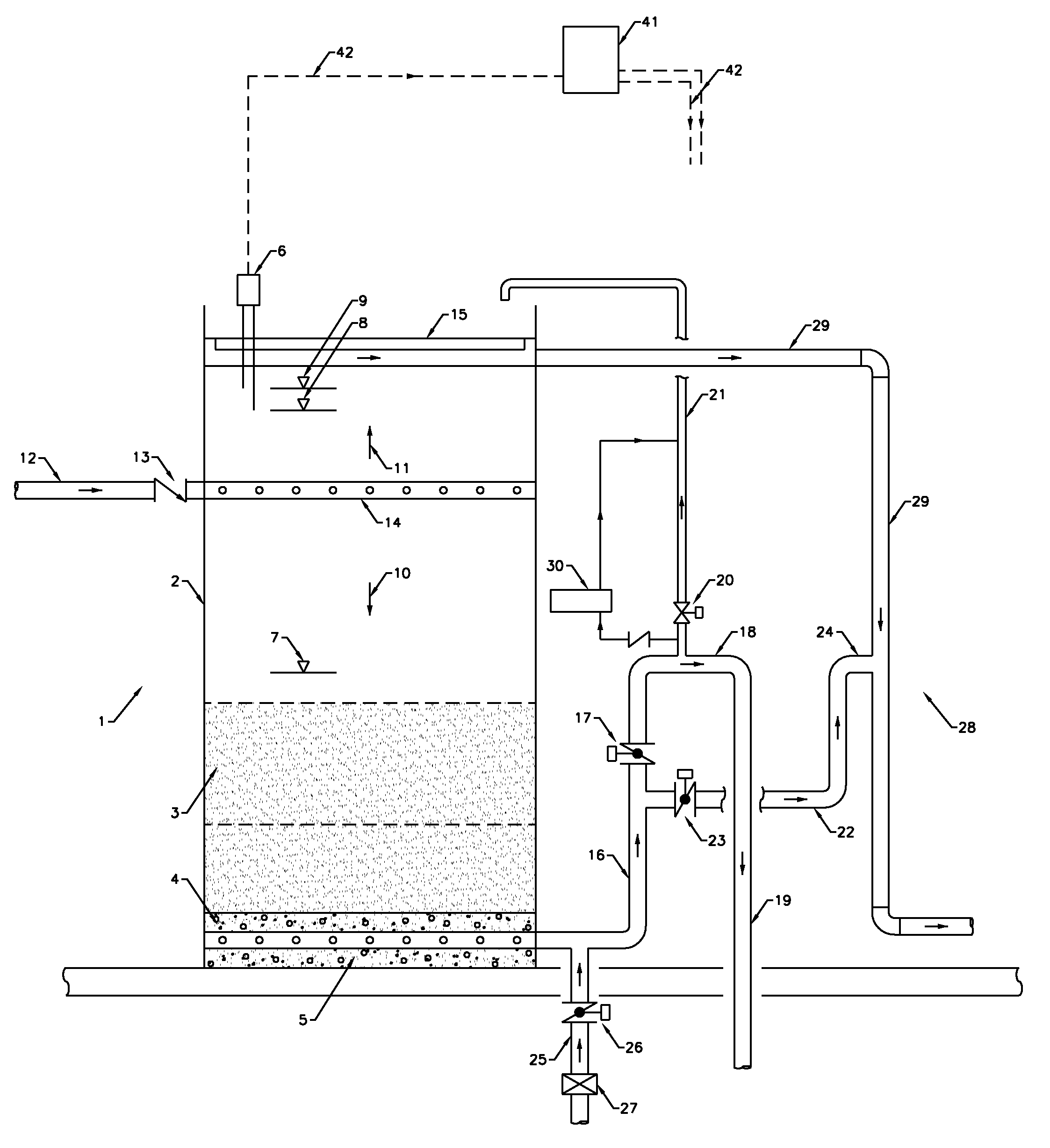
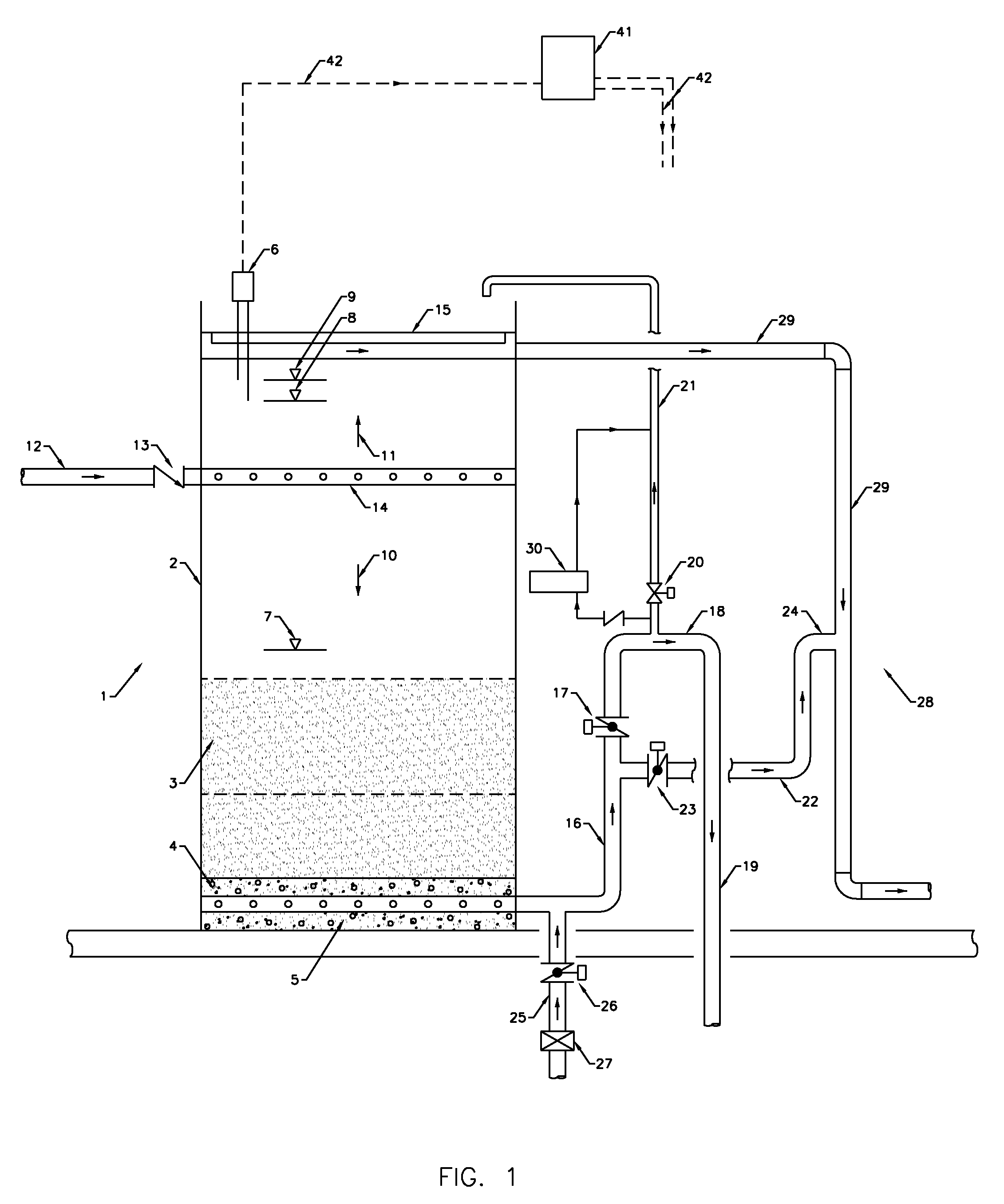
[0017]The filtration system as shown on FIG. 1 uses a novel siphon piping and control system design which results in a lower head room requirements, an extended filtration cycle, a less frequent backwashing, a lower backwash wastewater volume and a lower filtration down time.
[0020]The two-stage filtration system backwashing of the filtration media can be done separately for each stage or jointly for both stages which results in a reduction of the backwash water volume requirements.

Problems solved by technology

The backwash and rinse water is predominantly wasted.

Method used


Image

  • Syphon Filtration System
  • Syphon Filtration System
  • Syphon Filtration System

Examples


second embodiment

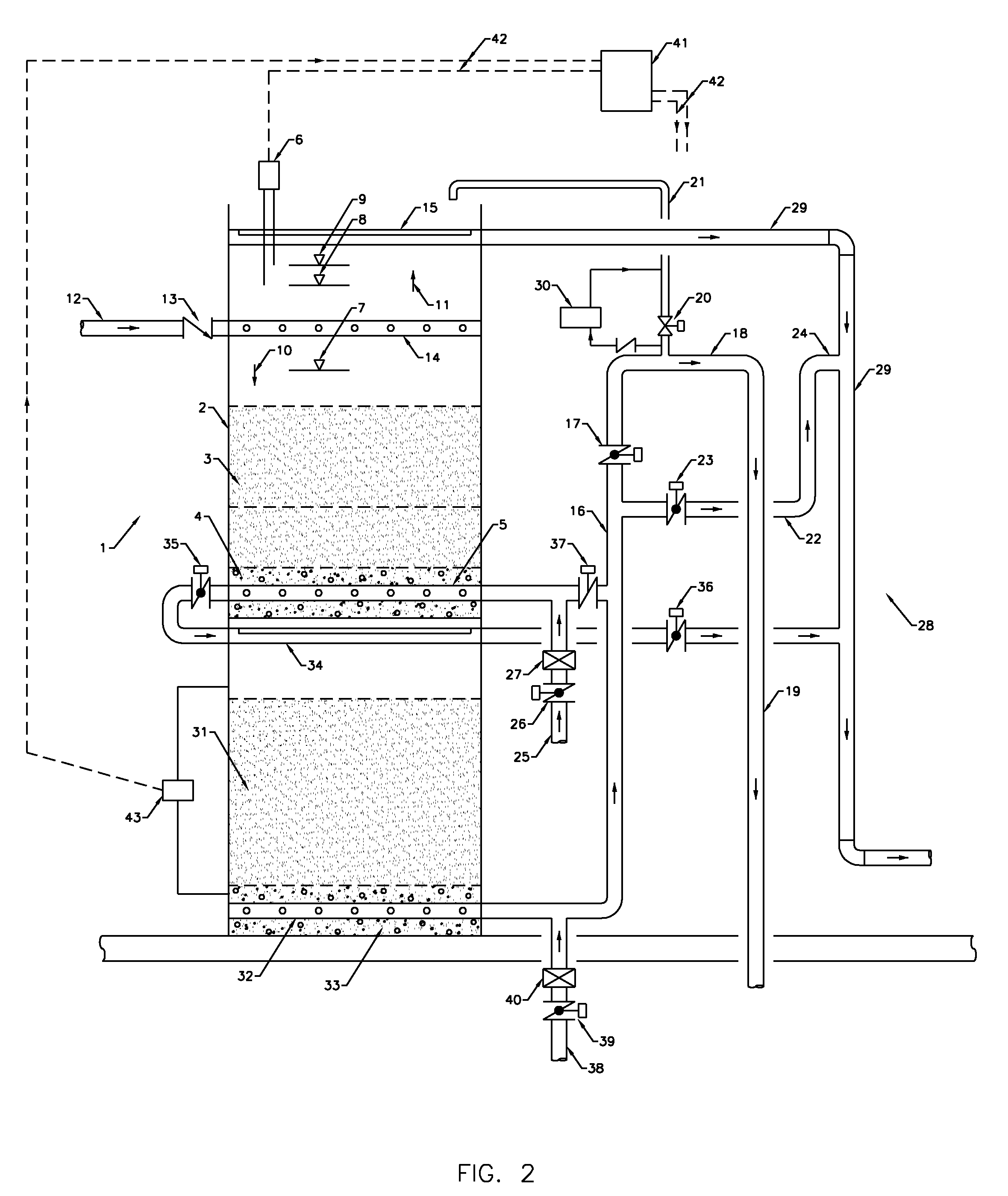
[0076]the invention is shown on FIG. 2.

[0077]For the various embodiments disclosed here, the same reference numeral numbers are used for the same or substantially similar features.

[0078]The filter vessel 2 comprises two independent filter media 3 and 31, two independent underdrain systems 4 and 32, two independent water outlet pipes 5 and 33, two independent backwash water collecting troughs 15 and 34, and two independent backwash water supply pipes 25&38 and control valves 26&39 and rate of flow control valves 27&40.

[0079]The other additional features comprised in this embodiment are control valves 35, 36&37, and a differential pressure switch 43.

first embodiment

[0080]The filter operating cycles are the same in this embodiment as those outlined in the first embodiment and they comprise:[0081]Filtration without the syphon action.[0082]Filtration with the syphon action.[0083]Backwashing.[0084]Rinsing.

[0085]The filter backwashing can be performed jointly or independently for both filter media 3 and 31 followed by a joint or independent rinsing cycles of each filter media respectively.

[0086]If a joint filter backwashing and rinsing cycles are performed for both filter media 3 and 31, the filter media 3 backwashing and rinsing cycles can be extended beyond those performed for the filter media 31 as required.

[0087]The various combinations of the backwashing and rinsing cycles are outlined as follows:[0088]Joint backwashing of both filter media 3 and 31:[0089]The control valves 35&39 are open, the backwash water supply is provided from pipe 38.[0090]The control valves 17, 20, 23, 36, 37&26 are closed.[0091]The backwash water flows upward through t...


PUM

PropertyMeasurementUnit
Pressureaaaaaaaaaa
Volumeaaaaaaaaaa
Levelaaaaaaaaaa

Abstract

A syphon filtration system is a low head, small foot print, long operating cycle, gravity filtration system for treatment of water and wastewater.The filtration system is an apparatus and process with one-stage or two-stage filtration process in one vessel. The filtration system can use different filtration media of sand, anthracite and activated carbon or other proprietary filtration media.The one-stage filtration system is applicable to removal of suspended solids or dissolved impurities.The two-stage filtration system can provide a combination of two different filtration processes for removal of suspended solids and dissolved impurities.The one-stage filtration system has low head room requirements, and the two-stage filtration system has small foot print requirements.In the two-stage filtration system, each filtration stage can be backwashed independently or both stages can be backwashed simultaneously.The filtration system uses novel syphon piping and controls design which extend the filtration operating cycle and reduce the filter apparatus headroom, and the filter backwash water volume requirements.

Description

FIELD OF THE INVENTION[0001]The invention is an apparatus and process for treatment of water and wastewater for removal of suspended solids and dissolved impurities.BACKGROUND OF THE INVENTION[0002]Filtration systems are used for treatment of water and wastewater for removal of suspended solids and dissolved impurities.[0003]The filtration systems are usually one-stage, gravity or pressure flow systems.[0004]The gravity flow filtration systems depend on a static water pressure (head) above the filter media for the water to flow through the media. The available static water pressure above the filter media is directly proportional to the filtration operating cycle before the filter media has to be backwashed. Therefore, the higher the filter vessel above the filter media the longer the operating cycle is expected for the same water quality and flow rate treated.[0005]The filtration systems are usually provided for removal of suspended solids or dissolved impurities and each usually re...

Claims


Application Information

Patent Timeline
IPC IPC(8): B01D24/12B01D35/00
CPCB01D24/008B01D2201/206B01D24/14B01D24/4631Y10T137/2829Y10T137/2849
Inventor KORZENIOWSKI, JAN A.
Owner KORZENIOWSKI JAN A
Learn More