Wireless Microactuator Motor Assembly for Use in a Hard Disk Drive Suspension, and Mechanical and Electrical Connections Thereto

a micro-actuator and suspension technology, applied in piezoelectric/electrostrictive transducers, instruments, record information storage, etc., can solve the problems of increasing the difficulty of motor and servo control system to quickly and accurately, the resolution and bandwidth of conventional actuator motors, such as voice coil motors (vcm), lacks sufficient bandwidth and resolution to effectively accommodate high-density disks, and adds a significant cost component to the finished suspension assembly. , to achieve the effect o

Active Publication Date: 2010-10-28
MAGNECOMP
View PDF19 Cites 79 Cited by
  • Summary
  • Abstract
  • Description
  • Claims
  • Application Information

AI Technical Summary

Benefits of technology

[0013]The present invention provides a mechanical bond and electrical interconnection for a PZT microactuator that does not require high temperatures and therefore does not suffer from depoling. The invention provides a method of making an actuator that is useful in a suspension assembly and that does not suffer from some of the drawbacks of the prior art. Specifically, a microactuator assembly containing a PZT bonded to stainless steel is prepared separately. The assembly can be prepared in a relatively dirty environment and at a relatively low temperature and then cleaned. The assembly can then be readily integrated into a suspension and mechanically and electrically connected to the suspension, such as to the stainless steel substrate from which the load beam is formed, using laser welding. In one embodiment, segmenting the base stainless steel allows a higher percentage of the original D31 to be attained in the repoling process. Silver containing conductive adhesives possessing sufficient resiliency and conductivity can be cured below the Curie temperature that would result in degradation of the D31 that would mandate re-polling of the PZT In a case where re-polling would be required, the segmented structures taught herein do not restrain the PZT as would a continuous sheet such as in Thunder or a standard PZT integrated into a suspension assembly using conventional methods. Additional advantages are that the assembly is relatively flat, and can be constructed separately and then later integrated into the suspension using standard laser welding processes that are clean and do not produce potentially contaminating particles.

Problems solved by technology

It becomes increasingly difficult for the motor and servo control system to quickly and accurately position the read / write head over the desired track.
Conventional actuator motors, such as voice coil motors (VCM), often lack sufficient resolution and bandwidth to effectively accommodate high track-density disks.
The control wires are sometimes referred to as a “tail weave.” The tail weave process is typically delicate and time consuming, thus adding a significant cost component to the finished suspension assembly.
One disadvantage to using a high temperature epoxy or other high temperature process to make mechanical and / or electrical connections to the PZT material is that upon cooling the PZT is under compression and is actually bowed due to the mismatches in coefficients of thermal expansion (CTE) between the stainless steel and the PZT.
Although a pre-bowed PZT is claimed by the marketers of the Thunder process to provide increased stroke length, the temperature encountered in high temperature lamination results in a de-poling of the PZT.
A further disadvantage to using adhesive to bond the PZT to the stainless steel is that the adhesive bonding process generally not compatible with the clean room requirements for assembling disk drives.
The adhesive bonding process can produce small stray particles that can lead to product defects.

Method used


Image

  • Wireless Microactuator Motor Assembly for Use in a Hard Disk Drive Suspension, and Mechanical and Electrical Connections Thereto
  • Wireless Microactuator Motor Assembly for Use in a Hard Disk Drive Suspension, and Mechanical and Electrical Connections Thereto
  • Wireless Microactuator Motor Assembly for Use in a Hard Disk Drive Suspension, and Mechanical and Electrical Connections Thereto

Examples


first embodiment

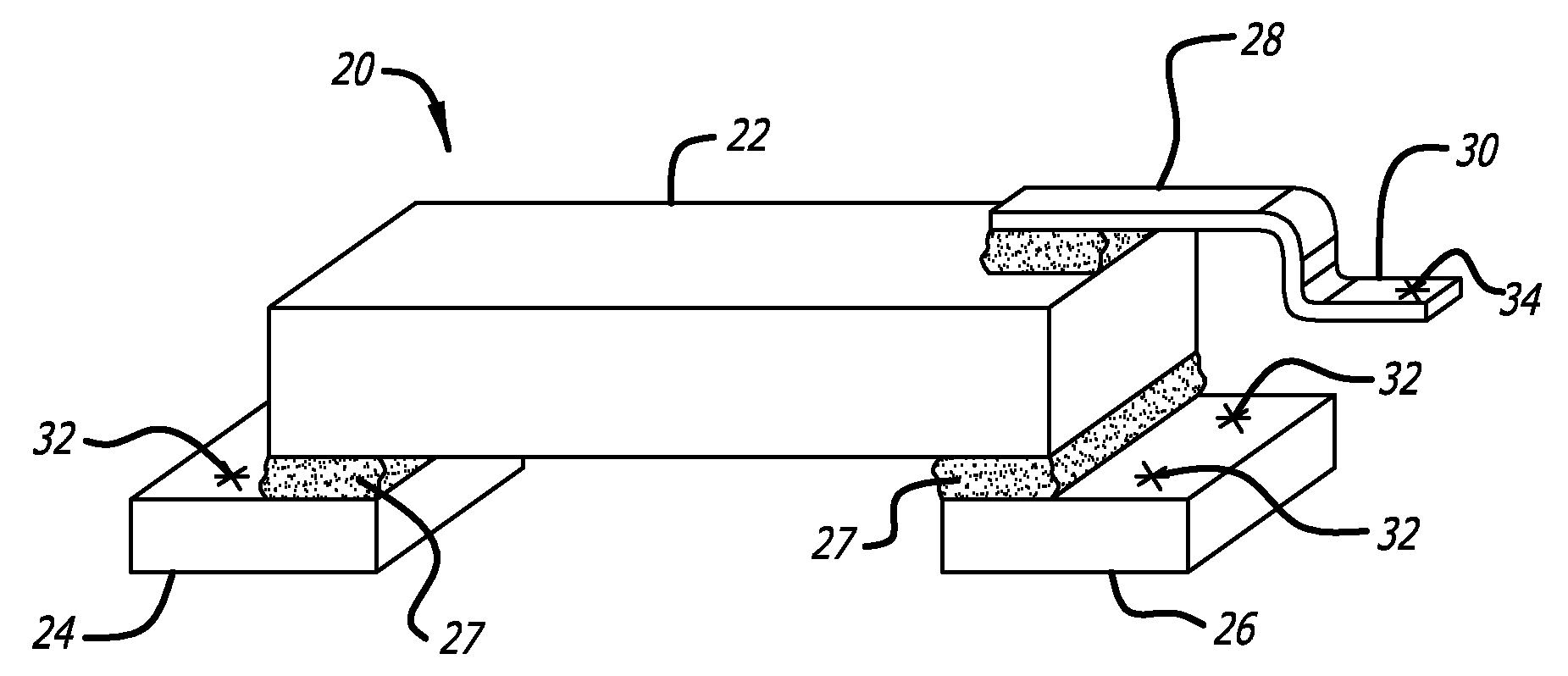
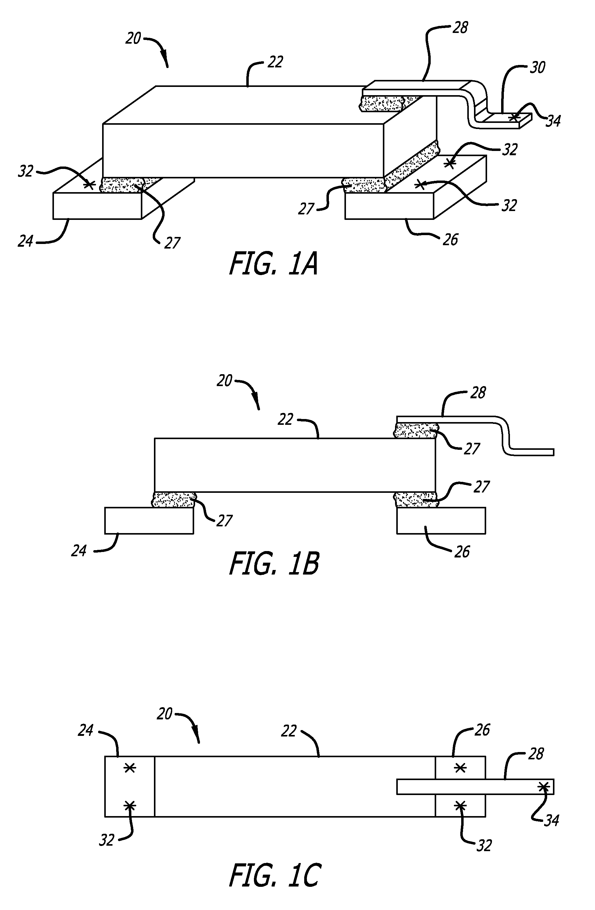
[0038]FIG. 1A is a side perspective view of a microactuator assembly according to the invention. First base 24 and second base 26 are affixed to the bottom surface of PZT element 22, the bottom surface being a negative electrode of PZT element 22. Bases 24 and 26 can be affixed to bottom of PZT element 22 using conductive adhesive 27 such as conductive epoxy, or by other methods as will be discussed later. Bases 24 and 26 are formed of a conductive material which is stainless steel that is preferably thin enough for laser welding, such as sheet stainless steel material. Bases 22 and 24 will be welded at weld locations 32. A top lead 28 made of a stainless steel sheet material, and thus generally flat and planar in shape, is attached to the top surface of PZT element 22 which is the positive electrode of PZT element 22. Top lead 28 has two bends formed in it, thereby forming a lead tab 30 which will be welded at weld location 34. In this embodiment bases 24 and 26 are separate compon...

second embodiment

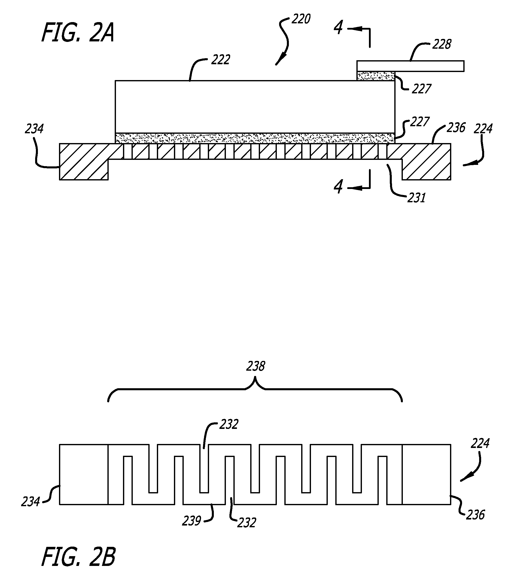
[0042]FIG. 2A is a side elevation view of a microactuator assembly according to the invention. In this embodiment, the two bases 234 and 236 located at opposite ends of PZT element 222 are fabricated out of a single unitary piece of material that defines a unitary base 224. A gap 231 is formed between bases 234 and 236 such as by chemical etching or laser etching. Unitary base 224 is affixed to the bottom surface which is the negative electrode of PZT element 222 by polyimide 227 which will be described in detail later with respect to FIG. 4. Similarly, top lead 228 is affixed to the top surface which is the positive electrode of PZT element 222 by polyimide 227.

[0043]FIG. 2B is a bottom plan view of the unitary base 224 of the microactuator assembly FIG. 2A. An expandable bridging section or connecting section 238 connects first base 234 to second base 236, thus rendering the PZT negative lead expandable between the two loci at which it is attached to the PZT. Expandable bridging s...

third embodiment

[0044]FIG. 3 is a side elevation view of a microactuator assembly according to the invention. In this embodiment, the feature in unitary base 324 that allows the base to expand is a series of accordion like folds 326. Alternatively, the expandable bridging section 238 could have corrugations in it that allow it to expand. Conductive adhesive 327 is used to affix the unitary base 324 and top lead 328 to PZT element 322.

[0045]FIG. 4 is a side cutaway view of the microactuator assembly of FIG. 2A taken along section line 4-4, showing details of the various materials that may be used to mechanically and electrically attach leads 228 and 224 to PZT element 222. PZT element 222 is first coated on both surfaces with a sputtered metal layer 240 such as nickel (Ni) or chromium (Cr). Next, a highly conductive layer 241 such as sputtered gold (Ag) or titanium (Ti) is applied. This renders the surface of PZT element 222 highly conductive so that charge from the associated lead is applied across...


PUM

PropertyMeasurementUnit
driving voltageaaaaaaaaaa
conductiveaaaaaaaaaa
flexibleaaaaaaaaaa

Abstract

A microactuator assembly for a hard disk drive head suspension has an expandable base of stainless steel sheet material defining a negative lead affixed to the negative electrode on the bottom surface of a piezoelectric element, and a piece of stainless steel sheet material defining a positive lead attached to the positive electrode on the top surface of the piezoelectric element. The leads may be affixed directly to the piezoelectric element via conductive adhesive. The microactuator assembly can be assembled separately, and then laser welded into place on a suspension. A bond pad made of stainless steel sheet material extends from the flexible circuit, is electrically connected to the microactuator driving voltage conductor within the flexible circuit through a via, and is electrically isolated from the suspension substrate by an insulating film. The microactuator unit positive lead is mechanically and electrically connected to the bond pad via laser welding.

Description

CROSS-REFERENCE TO RELATED APPLICATIONS[0001]None.BACKGROUND OF THE INVENTION[0002]1. Field of the Invention[0003]This invention relates to the field of microactuated hard disk drive suspensions. More particularly, this invention relates to the field of a wireless microactuator assembly for a hard disk drive suspension, and mechanical and electrical connections to the microactuator.[0004]2. Description of Related Art[0005]Storage of information has progressed through the years. From the early days, primitive man stored information on walls of caves, as well as used writings on wood such as bamboo. Since then, people have used wood, silk, and papers as a media for writings. Paper has been bound to form books. Information is now stored electronically on disks, tape, and semiconductor devices. As merely an example, some of the early disks used magnetic technology to store bits of information in a digital manner onto the magnetic media. One of the first disk drives was discovered in the...

Claims


Application Information

Patent Timeline
Patent Type & Authority Applications(United States)
IPC IPC(8): G11B5/56H01L41/22
CPCG11B5/5552H01L41/047H01L2224/45144Y10T29/42H01L2224/48137H01L2224/48091H01L2924/00014H01L2924/00G11B5/4873H10N30/875
Inventor SCHREIBER, CHRISTOPHER
Owner MAGNECOMP
Why Eureka
Try Eureka