Pre-Cooled Liquefaction Process

a liquefaction process and pre-cooled technology, applied in the direction of liquefaction, laminated elements, lighting and heating apparatus, etc., can solve the problems of limiting the applicability of cosub>2 /sub>based cycles, reducing the efficiency of the process, and preventing the removal of required amounts of impurities

Inactive Publication Date: 2010-11-11
AIR PROD & CHEM INC
View PDF13 Cites 50 Cited by
  • Summary
  • Abstract
  • Description
  • Claims
  • Application Information

AI Technical Summary

Benefits of technology

[0013]Embodiments of the present invention satisfy this need in the art by providing an improved liquefaction system and method that utili

Problems solved by technology

Use of CO2, therefore, may preclude the removal of required amounts of such impurities in the pre-cooling section.
Second, the critical temperature (i.e., the temperature above which a fluid cannot be condensed irrespective of pressure) of CO2 is approximately 31.1° C., which means that CO2 cannot be condensed above 31.1° C. A pre-cooling cycle, however, requires a condensed refrigerant which supplies refrigeration by boiling against a load stream.
Thus, if the sea water is warm, for example, 27° C., which is the typical surface water temperature in the tropical regions, and assuming a typical 10° C. approach in the condenser, the CO2 cannot be condensed using the mild sea water, thereby degrading the efficiency and limiting the applicability of CO2 based cycles for latitudes with sea water below approximately 20° C.
The use of special high pressure barrel type casings thereby raises the capital cost.
Thus, the whole system must be designed with high pressure piping, pressure relief devices, etc. that increase capital cost and increase gas pressure safety concerns, especially on an offshore platform where distances between equipment and personnel is much less than compared with land-based plants.
While propane has been widely used in land-based plants as a pre-cooling refrigerant, us

Method used


Image

  • Pre-Cooled Liquefaction Process
  • Pre-Cooled Liquefaction Process
  • Pre-Cooled Liquefaction Process

Examples


examples

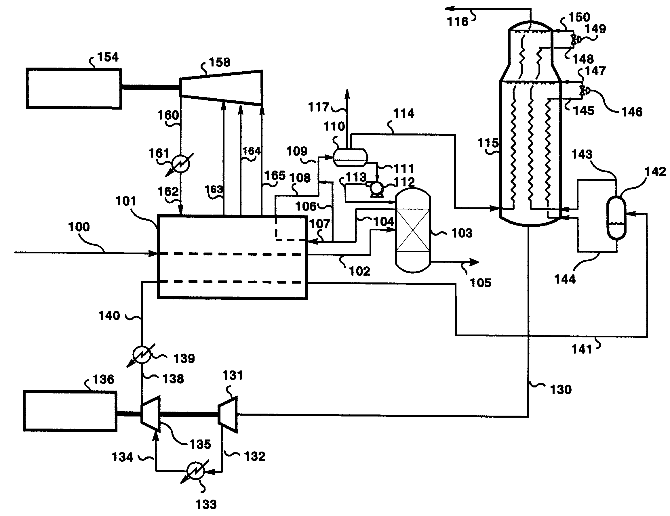
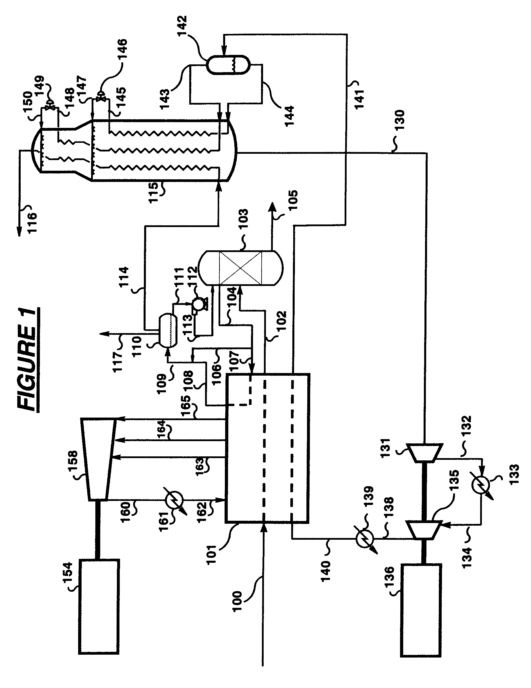
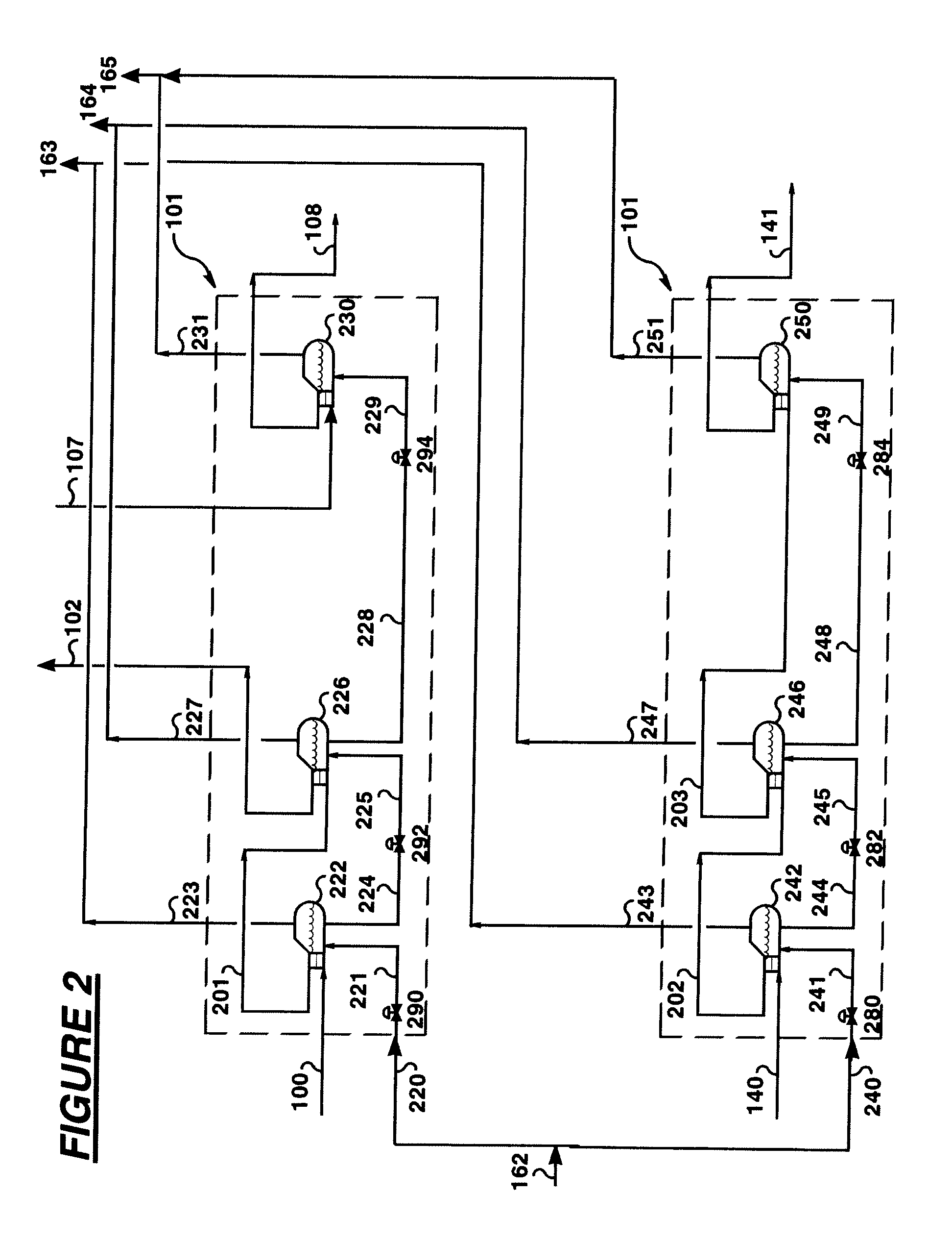
[0071]In this exemplary illustration, a dehydrated natural gas feed stream 100 was liquefied to form LNG using the HFC pre-cooled mixed refrigerant process. The total dehydrated natural gas feed stream 100 entering the pre-cooling section was around 2.39 mmtpa or 301.2 tph. The dehydrated natural gas feed stream 100 from the drier beds (not shown in FIG. 1) entered the HFC cooled evaporator 222 at 15° C. and 68.95 bara where it was cooled to a temperature of −4.06° C. The feed was further cooled in evaporator 226 to a temperature of approximately −24.39° C. after which it was sent to the scrub column 103 as stream 102. The cold reflux stream 111 in the scrub column 103 caused the stripping of the C3+ (propane, butanes, pentane etc.) hydrocarbons from the input stream 102 to yield a vapor overhead stream 104 and a bottoms heavy hydrocarbon stream 105.

[0072]Table 4 summaries the various stream conditions from the exemplary illustration:

TABLE 4Stream102104105Flowlbmol / h38,298.9435,757....


PUM


Abstract

A system and method for liquefying a natural gas stream, the method including the steps of providing a dehydrated natural gas stream for liquefaction, pre-cooling the dehydrated natural gas stream in a pre-cooling apparatus, where the pre-cooling is performed by using a pre-coolant that consists essentially of a hydroflorocarbon (HFC) refrigerant, further cooling the pre-cooled dehydrated natural gas stream in a main heat exchanger through indirect heat exchange against a vaporized hydrocarbon mixed refrigerant coolant to produce a liquefied natural gas product stream, where the mixed refrigerant coolant comprises ethane, methane, nitrogen, and less than or equal to 3 mol % of propane.

Description

BACKGROUND[0001]Previously pre-cooled natural gas liquefaction processes were disclosed for use on Floating Production Storage and Offloading platforms (FPSO's) that used CO2 to pre-cool a natural gas feed stream while a mixed refrigerant hydrocarbon mixture (HMR) was used to further cool the pre-cooled stream to provide a liquefied natural gas (LNG) product. In these processes, the natural gas feed stream is pre-cooled against boiling CO2 at one or more pressure levels. The CO2 vaporizes while pre-cooling the natural gas feed stream to a temperature of approximately −35° C. The CO2 vapors are then compressed, cooled, and condensed to form the liquid CO2 refrigerant to be re-circulated back into the process.[0002]Using CO2 as a precoolant for liquefaction of LNG on a FPSO, however, has several disadvantages. First, CO2 has a freezing point of −56.6° C. at which temperature dry ice formation begins to occur. To prevent operational issues associated with the formation of dry ice in a ...

Claims


Application Information

Patent Timeline
IPC IPC(8): F25J1/00F25J3/06F28F3/00
CPCC09K5/041F25J2290/02F25J1/0022F25J1/0052F25J1/0055F25J1/0087F25J1/0092F25J1/0097F25J1/0214F25J1/0238F25J1/0241F25J1/0278F25J1/0283F25J1/0284F25J1/0292F25J1/0298F25J2220/64F25J2280/10F25J1/0215F25J1/0216F25J1/025F25J1/0256F25B9/006F25J1/004F25J1/021
Inventor ROBERTS, MARK JULIANVARMA, VISHAL ANANDSWARUP
Owner AIR PROD & CHEM INC
Why Eureka
Try Eureka