Roll-to-roll glass material attributes and fingerprint

a technology of fingerprint and glass, applied in the field of glass sheets, can solve the problems of unsatisfactory surface quality, added expense, and unsatisfactory surface quality, and achieve the effect of high surface quality

Active Publication Date: 2010-11-18
CORNING INC
View PDF16 Cites 34 Cited by
  • Summary
  • Abstract
  • Description
  • Claims
  • Application Information

AI Technical Summary

Benefits of technology

[0003]An additional method for forming glass sheet materials is the fusion draw process. In this process, molten glass is fed into a trough called an “isopipe,” which is overfilled until the molten glass flows evenly over both sides. The molten glass then rejoins, or fuses, at the bottom of the trough where it is drawn to form a continuous sheet of flat glass. Because both major surfaces of the glass sheet do not directly contact any support material during the forming process, high surface quality in both major surfaces can be achieved.

Problems solved by technology

However, float glass processes necessarily involve direct contact between the glass melt and the molten metal, which can lead to undesired contamination at the interface and less than pristine surface quality.
In order to produce high quality float glass sheets with pristine surface properties on both major surfaces, float glass is typically subjected to surface polishing steps, which add additional expense.
Moreover, it is believed that the float process has not been used to make ultra-thin, rollable glass sheets.
Due to the dynamic nature of the fusion draw process, the number of glass compositions suitable for fusion draw processing is limited to those that possess the requisite properties in the molten phase (e.g., liquidus viscosity, strain point, etc.).
Further, although relatively thin glass sheets can be made via fusion draw, the process cannot be used to form ultra-thin, rollable high-silica glass sheets.
Finally, the apparatus used in the fusion draw process can be expensive.
In addition to their limitations with respect to ultra-thin glass sheet materials, both float and fusion draw processes are largely impractical sheet-forming methods for high-silica glass sheets due to the high softening point (˜1600° C.) of silica.
Such a batch approach is extremely expensive and wasteful.
Indeed, the requisite slicing and polishing that would be needed to produce uniform, thin, flexible silica glass sheets via flame-hydrolysis render the process prohibitively expensive.
Using known methods, Applicants believe that it is not currently feasible to form and polish both sides of a high-silica glass sheet having a thickness of less than 150 microns.

Method used


Image

  • Roll-to-roll glass material attributes and fingerprint
  • Roll-to-roll glass material attributes and fingerprint
  • Roll-to-roll glass material attributes and fingerprint

Examples


example 1

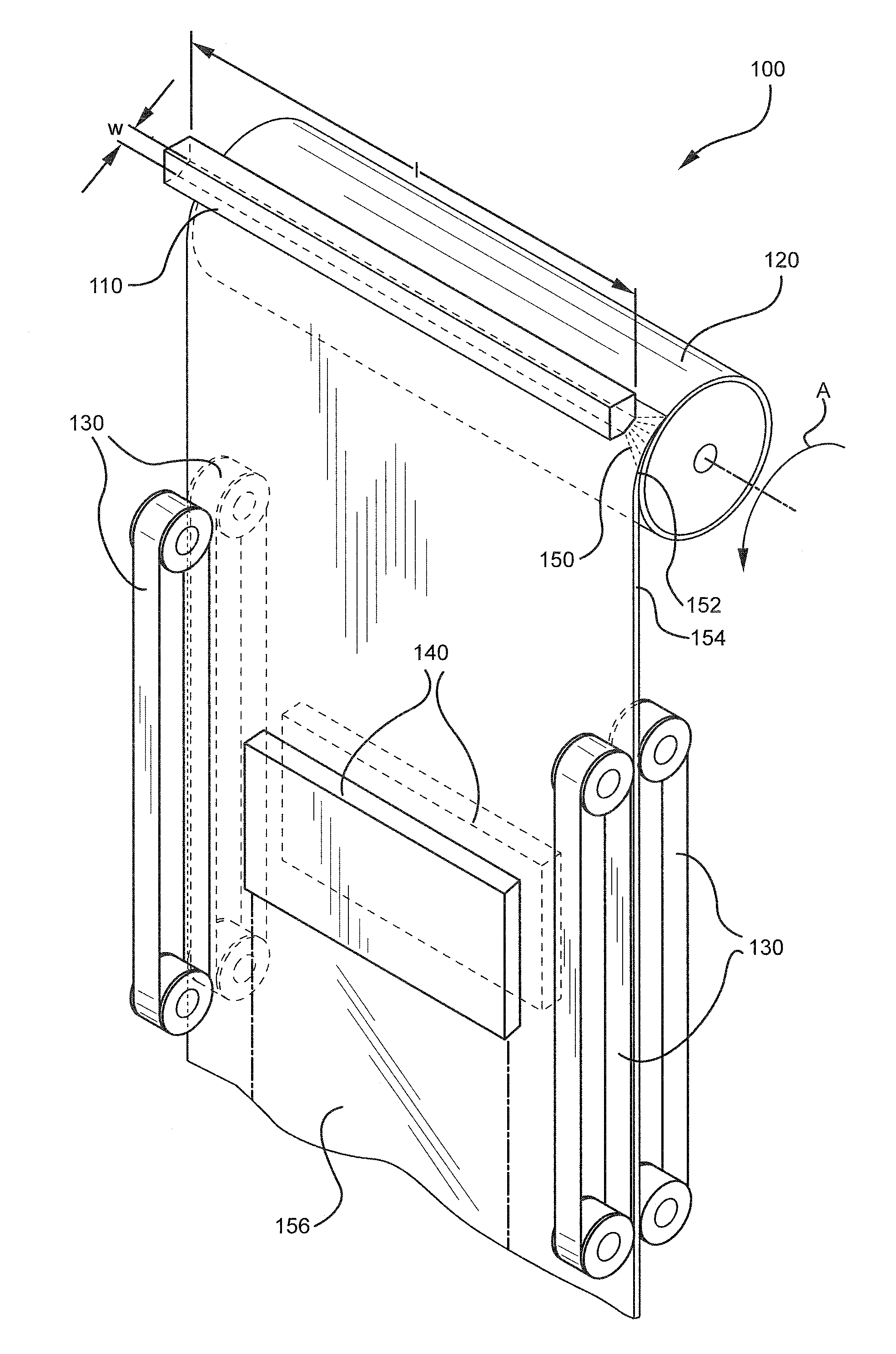
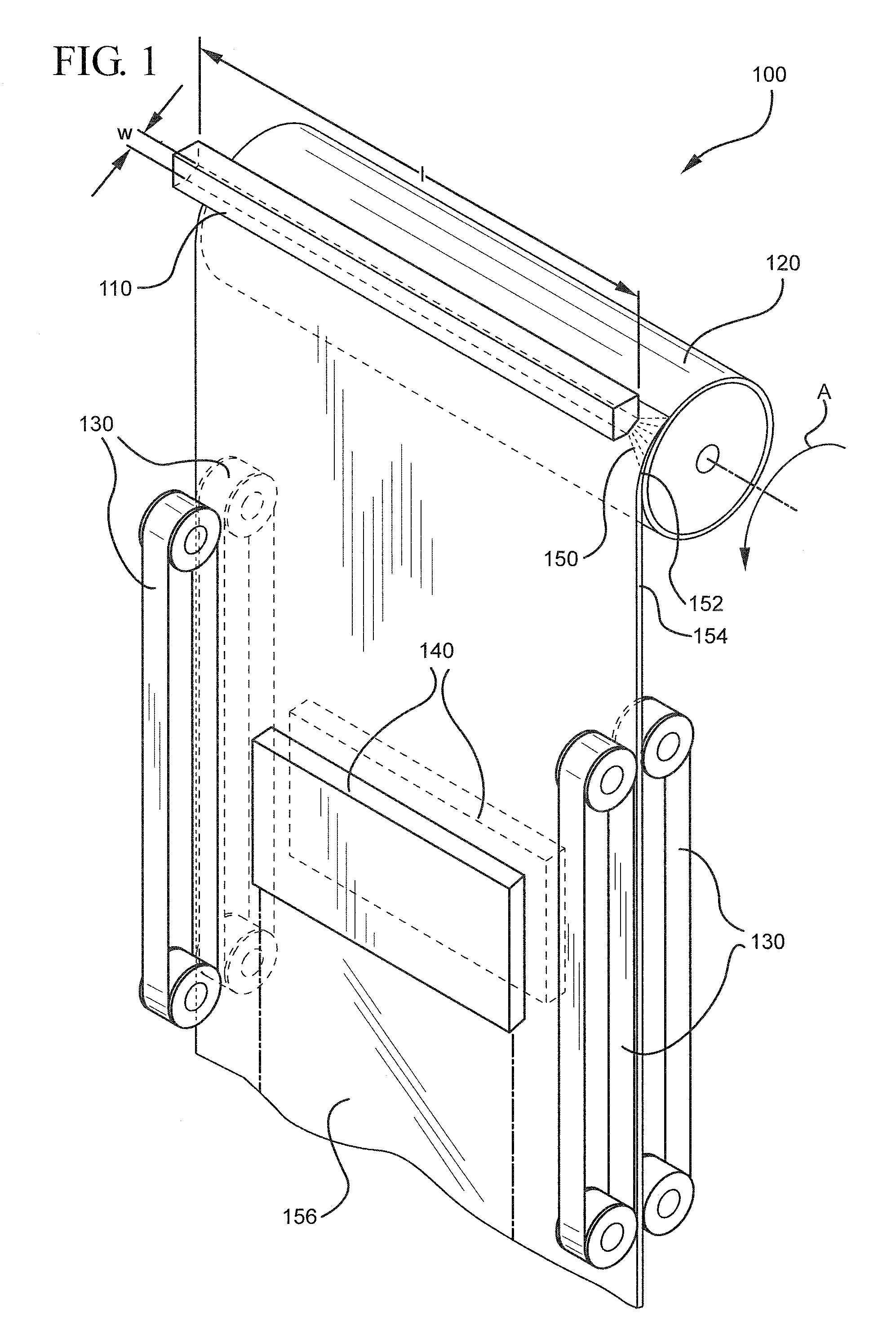
Fabrication of a Single-Layer Soot Sheet

[0072]A soot layer comprising 99+ mole % silica was produced using five linear burners. The five 2.5 cm wide burners were mounted adjacently in a burner array to produce a uniform, 12.5 cm wide soot stream. Each burner included 9 parallel rows of gas orifices. The gas orifices each measure 0.075 cm in diameter.

[0073]A precursor gas mixture comprising OMCTS (5 g / min) entrained in N2 (20 SLPM) was flowed through the centerline row of orifices. Oxygen gas was flowed through three adjacent rows of orifices on each side of the centerline row. The oxygen gas flow through the immediately adjacent rows was 5 SLPM, while the oxygen gas flow through the next pair of rows was 20 SLPM. The gas flow through the final (outside) orifice rows comprised a mixture of CH4 (12 SLPM) and O2 (10 SLPM).

[0074]The burners were positioned approximately 10 cm from the deposition surface of a cylindrical soot-receiving device. The soot-receiving device had a diameter of ...

example 2

Sintering of a Single-Layer Soot Sheet

[0076]A soot sheet as described above in Example 1 but having a thickness of about 400 microns was fabricated. The thickness was increased by decreasing the rotation speed of the soot-receiving device and increasing the OMCTS flow rate.

[0077]A soot sheet measuring approximately 1.2 m long and 7.6 cm wide was sintered by first gripping peripheral edges of the soot sheet between rollers that maintained contact along the length of the sample within a sintering zone, and then passing the soot sheet through a heat source that heated the soot sheet to approximately 1500° C. to form a densified, clear, sintered glass. The sintered glass had a final thickness of approximately 100 microns.

[0078]The sintered sheet having un-sintered peripheral edges was removed from the gripping rollers and the un-sintered edges were trimmed using a laser that was traversed at approximately 3 mm / s along the length of the sheet.

example 3

Effect of Process Conditions on Soot Sheet Thickness and Density

[0079]A designed experiment was conducted in which the (i) rotational velocity of the soot-receiving device, (ii) distance from the burner to the deposition surface, and (iii) 02 flow rate in the outermost burner columns (i.e., columns 1 and 9) were systemically varied. The effects of these variables on the thickness and density of the resulting soot sheet were measured and the data is shown in Table 2. Using the selected parameters, as seen in the tabulated data, a thickness of the soot sheet varies from about 250 to 700 microns, and a bulk density of the soot sheet varies from about 0.35 to 0.7 g / cm3. Generally, the soot sheet thickness and density increase with decreasing velocity of the soot-receiving device.

TABLE 2Effect of process conditions on soot sheet thickness and bulk densityBurner-DepositionSootBulk SootRunVelocitySurfaceO2ThicknessDensity#[mm / sec]Distance [mm][slpm][μm][g / cm3]1327.9263500.372227.9305000.40...


PUM

PropertyMeasurementUnit
thicknessaaaaaaaaaa
surface roughnessaaaaaaaaaa
thicknessaaaaaaaaaa

Abstract

A high-silica glass sheet has an average thickness of less than 150 microns and an average surface roughness over one or both of its two major surfaces of less than 1 nm. The glass sheet is formed using a roll-to-roll glass soot deposition and sintering process. The glass sheet may comprise a plurality of substantially parallel surface protrusions, which are visible only when a major surface of the glass sheet is viewed at an angle sufficiently removed from normal incidence.

Description

BACKGROUND AND SUMMARY[0001]The present invention relates generally to glass sheets and more specifically to sintered glass sheets such as silica glass sheets made using a glass soot deposition and sintering process.[0002]Glass sheet materials can be formed using a variety of different methods. In a float glass process, for example, a sheet of solid glass is made by floating molten glass on a bed of molten metal. This process can be used to form glass sheets having uniform thickness and very flat surfaces. However, float glass processes necessarily involve direct contact between the glass melt and the molten metal, which can lead to undesired contamination at the interface and less than pristine surface quality. In order to produce high quality float glass sheets with pristine surface properties on both major surfaces, float glass is typically subjected to surface polishing steps, which add additional expense. Moreover, it is believed that the float process has not been used to make...

Claims


Application Information

Patent Timeline
Patent Type & Authority Applications(United States)
IPC IPC(8): B32B3/00B32B3/30
CPCC03B19/1407Y10T428/24355Y10T428/2457C03B19/1492
Inventor HAWTOF, DANIEL WARRENNONI, JR., DOUGLAS MILES
Owner CORNING INC
Why Eureka
Try Eureka