Hydraulic drive with an independent charge pump

a charge pump and hydraulic drive technology, applied in the direction of fluid couplings, positive displacement liquid engines, servomotors, etc., can solve the problems of increasing the material expenditure in the cooling system the drive system suffers from power loss, and the hydraulic machine is prone to clogging. the problem of the hydraulic machine, so as to achieve the effect of increasing the expenditure of components and control measures

Active Publication Date: 2010-11-25
DANFOSS POWER SOLUTIONS INC
View PDF4 Cites 5 Cited by
  • Summary
  • Abstract
  • Description
  • Claims
  • Application Information

AI Technical Summary

Benefits of technology

[0009]The electric motor is controlled by means of electronics which are preferably integrated into the driving electronics of the hydraulic drive. The electronics may also be independent of the driving electronics. The electronics receive signals from a pressure sensor which is arranged on the high-pressure side of the charge pump and which determines the pressure generated by the latter. The electric motor is accordingly activated in such a way that the charge pump provides at all times a sufficient, preferably constant pressure for the operation of the hydraulic drive. The operation of the charge pump, in particular the volume flow and pressure generated by the latter, is hereby completely independent of the rotational speed and the power demands of the internal combustion engine. The charge pump can therefore reliably provide the required charge pressure in all operating states of the hydraulic drive. Here, it is to be considered a particular advantage that the charge pump always generates only the pressure and volume flow which is presently required, such that no components or control measures are required for dissipating excess pressurized fluid. In this way, all losses resulting from the overdimensioning of the charge pump, which is necessary according to the prior art, are eliminated.

Problems solved by technology

The power required for this can be up to 20% of that of the main pump, and is therefore considerable.
This leads to considerable power losses in the drive system, in particular at relatively high rotational speeds of the drive.
Furthermore, coolants are required for dissipating the heat energy, which entails an increased material expenditure in the cooling system of the hydraulic machine.
Although the charge pump itself can hereby be of smaller dimensions than previously conventional, said solution does however entail increased expenditure in terms of components and control measures.

Method used


Image

  • Hydraulic drive with an independent charge pump
  • Hydraulic drive with an independent charge pump
  • Hydraulic drive with an independent charge pump

Examples


Embodiment Construction

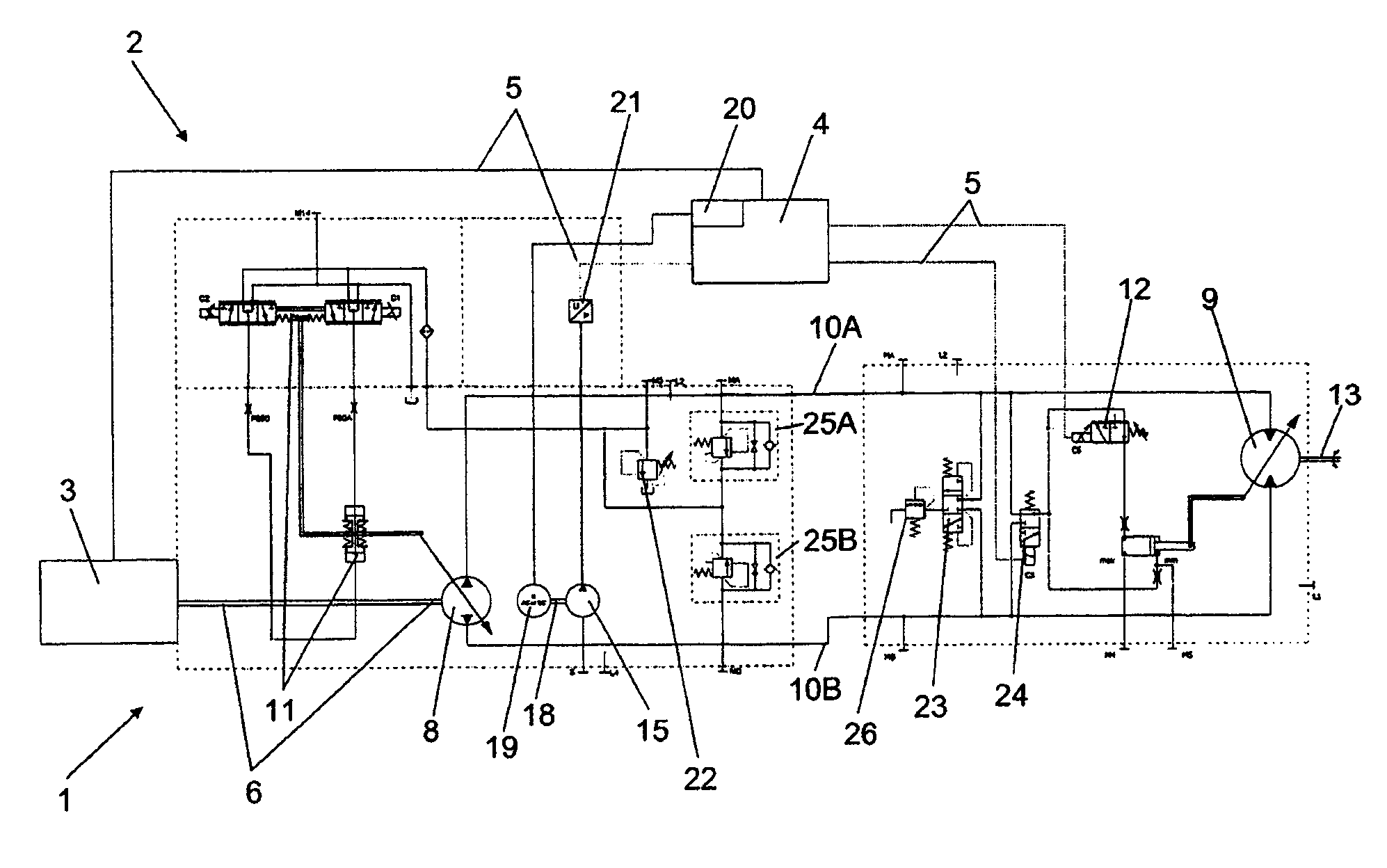
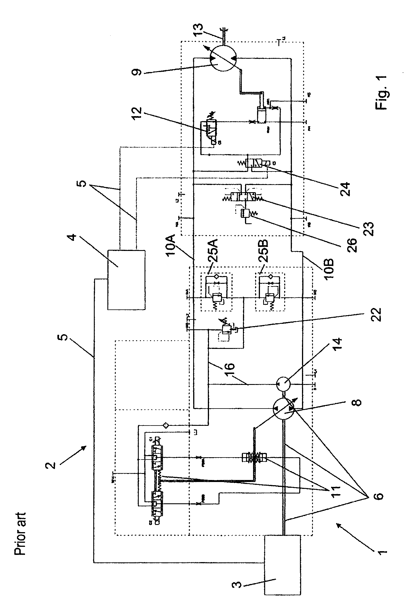
[0017]FIG. 1 illustrates, in a schematic view, a traction drive 1 having a hydraulic drive 2 according to the prior art. An internal combustion engine 3, usually a diesel engine, serves as a drive for the hydraulic drive 2 and is connected to the electronics 4, in this case driving electronics, via electric signal lines 5. The drive output shaft 6 of the internal combustion engine 3 drives the main pump 8 of the hydraulic drive 2 directly or via a step-up gearing (not shown). Said main pump 8 is connected in a closed circuit, via pressure lines 10A and 10B, to the hydraulic motor 9, illustrated here as a variable displacement motor. The main pump 8 can be adjusted in terms of delivery volume and delivery direction by means of the mechanical-hydraulic servo adjusting arrangement 11, which adjustment takes place according to driving demands which are input into the electronics 4 by the operator of the traction drive 1. The electronics 4 also acts on the motor adjusting arrangement 12 ...


PUM


Abstract

The invention relates to a hydraulic drive (2) having a main pump (8), which can be adjusted in terms of delivery volume and delivery direction, and having a hydraulic motor (9), which main pump (8) and hydraulic motor (9) are connected to one another in a closed circuit via pressure lines (10A, 10B), and having a charge pump (14, 15) for charging into the closed circuit and for supplying pressurized fluid to at least one controling device (11, 12), wherein the charge pump (15) has a separate drive motor (19) whose power/rotational speed can be specified independently of the rotational speed of the drive (3) of the main pump (8). In this way, the charge pump (15) can be of smaller dimensions than previously conventional, and the power balance of the hydraulic drive can be improved.

Description

BACKGROUND OF THE INVENTION[0001]The invention relates to a hydraulic drive having a main pump, which can be controlled in terms of delivery volume and delivery direction, and having a hydraulic motor, which main pump and hydraulic motor are connected to one another in a closed circuit via pressure lines, and having a charge pump for charging into the closed circuit and for supplying pressurized fluid to at least one control device, as per the preamble of Claim 1.[0002]A hydraulic drive of said type is known from DE 102 14 598 A1. Similar hydraulic drives are also described in documents DE 41 11 921 C2, DE 102 38 614 A1, DE 199 30 997 B4 and DE 100 37 195 A1. In such hydraulic drives, the charge pump has the function of providing pressurized fluid for the actuation of the control devices at least for the main pump and / or the variable displacement motor, and of compensating oil losses as a result of leakages in the closed circuit. The charge pump must be dimensioned for this purpose ...

Claims


Application Information

Patent Timeline
Patent Type & Authority Applications(United States)
IPC IPC(8): F15B11/08
CPCF04B49/002F15B7/006F15B7/008F15B7/10F15B2211/20515F15B2211/7058F15B2211/20553F15B2211/20561F15B2211/20584F15B2211/6309F15B2211/20523
Inventor RAMM, FRANK
Owner DANFOSS POWER SOLUTIONS INC
Why Eureka
Try Eureka