

Sodium cyanide process
a sodium cyanide and process technology, applied in the direction of alkali metal cyanides, chemistry apparatus and processes, inorganic chemistry, etc., can solve the problems of complex and expensive rectification and isolation procedures, and achieve the effect of improving the stability and stability of the reaction
- Summary
- Abstract
- Description
- Claims
- Application Information
AI Technical Summary
Problems solved by technology
Method used
Image

Examples
example 1
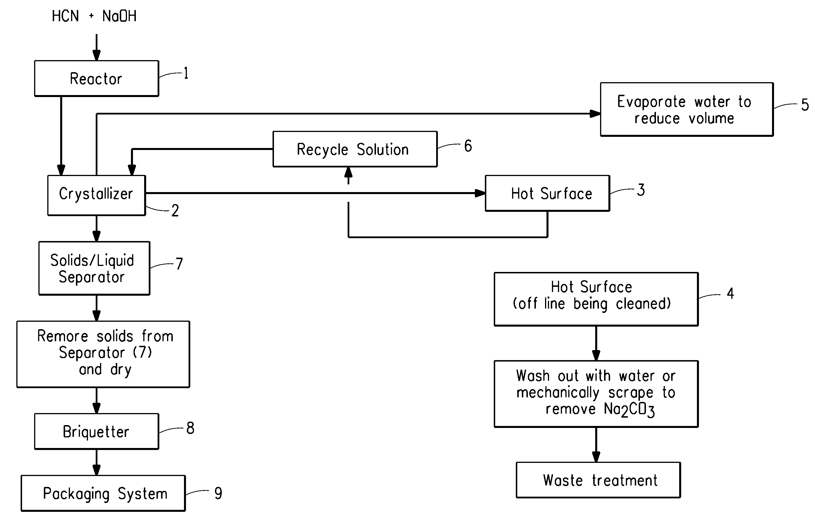
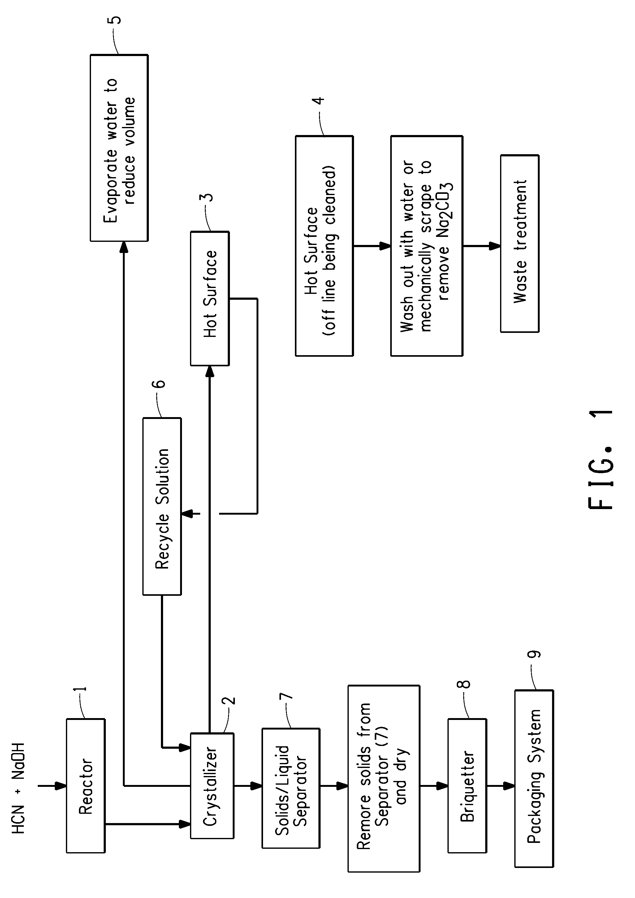
[0030]Reference numbers used in this Example refer to FIG. 1. Sodium hydroxide, commercially available from PPG Industries Inc., Pittsburgh, Pa., was fed into a reactor 2 feet by 8 feet (0.6 m by 2.4 m) in size, denoted as Reactor 1. Impure hydrogen cyanide gas, generated using a conventional Andrussow process, was fed directly from the HCN synthesis into Reactor 1 at a rate of 87,700 pounds per hour (39,150 kg per hour). The impure gas contained hydrocyanic acid, water, ammonia, methane, hydrogen, nitrogen, and carbon oxides. The contact time of the HCN with the NaOH in Reactor 1 was from about 0.06 to about 0.1 second. The alkalinity of the NaOH solution was controlled so that the percent NaOH was from about 0.1 to about 2.0 weight percent exiting the Reactor 1. The temperature was maintained at about 55° C. to about 75° C. during contacting of the HCN and NaOH. Direct absorption of the HCN gas by the NaOH solution occurred upon contact to produce NaCN solution. The NaCN solution ...
example 2
[0031]Example 2 employed the Environmental Simulation Program (The ESP®) software, commercially available from OLI Systems, Inc., Morris Plains, N.J., validated against Example 1. The same process conditions as Example 1 above were employed except that the contact time of the HCN with the NaOH in Reactor 1 was increased to about 0.5 seconds, and the process was alternated between two hot surfaces instead of temporarily stopping the process for cleaning of the surface. All other aspects of this Example 2 were the same as Example 1. The result of the change in contact time was that the alternation frequency between hot surfaces was significantly increased (on the order of five times) relative to that described in the previous Example 1. The NaCN crystals were indicated to be of greater than 98% purity.
example 3
[0032]Example 3 employed The ESP®, commercially available from OLI Systems, Inc., Morris Plains, N.J., as in Example 2 and was validated against Example 1. The same process conditions as Example 1 above were employed except that the alkalinity of the NaOH solution was controlled so that the percent NaOH was less than about 1.0 weight percent exiting the Reactor 1, and the process was alternated between two hot surfaces instead of temporarily stopping the process for cleaning of the surface. All other aspects of this Example 3 are the same as Example 1. The result of the change NaOH concentration was that the alternation frequency between hot surfaces was significantly decreased (on the order of four times) relative to that described in the previous Example 1. The NaCN crystals were indicated to be of greater than 98% purity.
PUM
| Property | Measurement | Unit |
|---|---|---|
| contact time | aaaaa | aaaaa |
| time | aaaaa | aaaaa |
| temperature | aaaaa | aaaaa |
Abstract
Description
Claims
Application Information