Method for forming a gear

a gear and gear technology, applied in the field of gear formation, can solve the problems of poor precision, surface decarburization, and difficult control of final gear roughness, and achieve the effects of reducing the number of times the mold is used in mass production, reducing the chance of mold collapse, and reducing the loading of the mold during formation

Inactive Publication Date: 2010-12-02
METAL INDS RES & DEV CENT
View PDF7 Cites 12 Cited by
  • Summary
  • Abstract
  • Description
  • Claims
  • Application Information

AI Technical Summary

Benefits of technology

[0014]The present invention is characterized in that the manufacturing process of the present invention uses an exhaustive progressive cold forging forming method, in which a refined horizontal forging machine is primarily utilized for progressive operation to produce a large quantity of gear within a short period of time, thereby providing a huge advantage to the manufacturing process technology. The principle of the present invention is to change the original single-process cold upsetting forming method of the prior art to a six-processes gear forming method the present invention, because the enormous load in the original single-process cold upsetting forming method causes the mold to collapse (predominantly punch fractures). The gear forming method the present invention uses the first five processes to design volume distribution to reduce the load step by step before carrying out the final formation of the gear, and complete pre-forging and pre-forming of the gear. Finally, in the sixth process, the gear is formed within certain machine equipment specifications (total processes are predominantly within six processes).
[0015]As described above, in the manufacturing process of the present invention, the load is reduced after passing multi-processes, which also substantially reduce the loading of the mold during formation and the chances of mold collapse as well. Besides, it can also increase the number of times the mold used in mass production (the lifetime of mold is prolonged), thereby substantially reducing production costs, and increasing yield rate.
[0016]The precision of conventional hot forging process is often affected by an oxidized skin scale layer and a surface decarburization layer, thus substantial manpower is required in the latter high-precision cutting process. However, the manufacturing process of the present invention eliminates the conventional hot forging process, such that not only processing costs but also material waste can be reduced.
[0017]The manufacturing process of the present invention eliminates the conventional hot-cold gear forging method, in which a cold forging finishing method is adopted to replace traditional high-precision cutting post-processing because of poor precision of hot forging methods. In addition, the manufacturing process of the present invention is also able to reduce mold change time required for hot-cold forging, and may complete formation of the gear by a single cold forging operation, thus, processing time and cost can be substantially reduced.
[0018]The present invention first carries out forming a high-precision inner hole, takes the inner hole as a criterion, and uses pressing process to form an outer tooth shape, thereby enabling inner hole precision when the gear is configured and the configuration precision when the gear is assembled to achieve a precision within the required tolerance, and increasing transmission effectiveness of the gear.
[0019]The micro-gear progressive cold forming method used in the present invention is provided with many characteristics, including: high precision, enabling avoid dimensional error caused by the hot forging; reducing miscellaneous processing and mold matching during the process of hot forging to cold forging; uses multi-processes forming load distribution to break through the bottleneck of forming micro-gears by using cold forging; by adopting an exhaustive cold forming method, the material easily adapts to strain conditions, resulting in better mechanical strength, and thereby enabling the lifetime of the gears to be substantially increased.

Problems solved by technology

However, the major shortcoming of the aforementioned hot forging forming method lies in that in the gear forming process, the billet (such as rod-shaped material) is heated to above the recrystallization temperature which often results in separation of the oxidized scale and causes surface decarburization after the gear is formed, such that the dimensional precision and the surface roughness of the final gear are hard to be controlled and may exceed the acceptable tolerances, resulting in that precision is too poor to be used in the manufacture of micro-gears.
However, although the hybrid way of hot and cold forgings can increase the precision of micro-gears in dimension, the oxidized scale and the surface decarburization layer portions caused by the hot forging are required to be processed in advance, thereby increasing time-consuming.
With regard to the desire to develop micro-gears (having a modulus below 1, and number of teeth of around 13 to 20), because of the work hardening easily formed during instantaneous cold forging, thus, an enormous deformation resistance load is produced, resulting in it being difficult to form micro-gears, even causing die-punch fractures.

Method used


Image

  • Method for forming a gear
  • Method for forming a gear
  • Method for forming a gear

Examples


Embodiment Construction

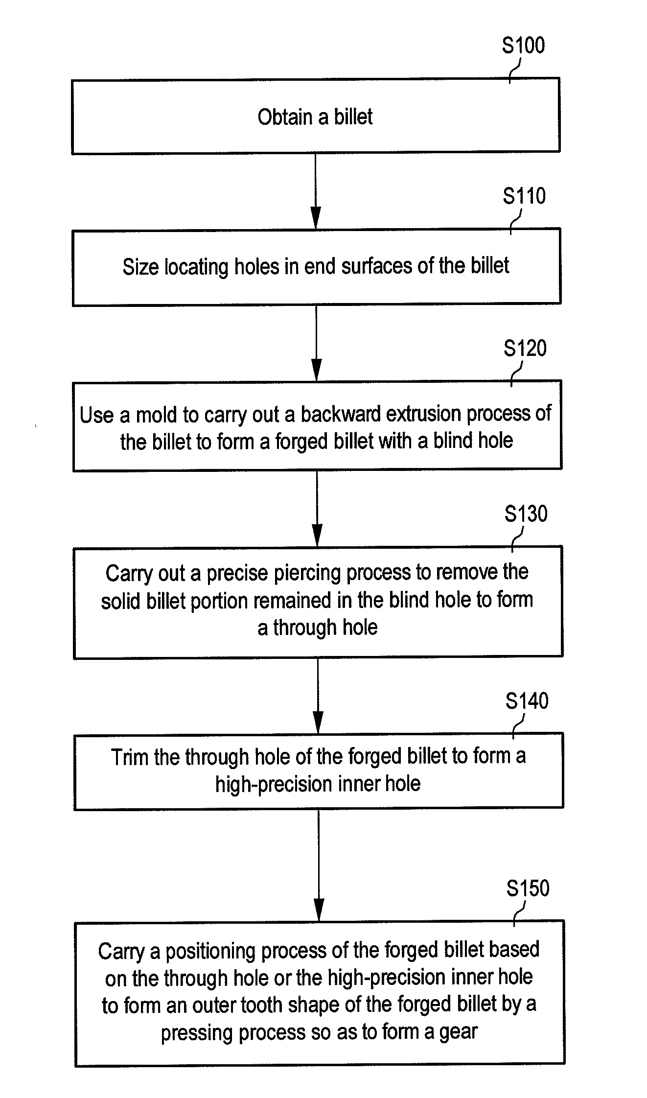
[0031]Referring first to FIG. 2, which shows a flow chart depicting a gear progressive cold forging forming method according to an embodiment of the present invention, and steps in the formation of the gear comprise steps as follows:

[0032]A billet 10 is obtained, and the billet 10 used in general forging of gears is rod-shaped metallic material, such as carbon steel, and the rod-shaped metallic material is cut to an appropriate length to serve as the billet 10 waiting to be machined (Step S100). Please also refer to FIG. 3A depicting a schematic structural view of a billet according to an embodiment of the present invention.

[0033]Two locating holes 11 are respectively sized in two end surfaces of the billet 10 where is vertical to axial direction of the billet 10 (Step S110), such that the billet 10 can be fixed in the correct position of a forming mold of the processing equipment. Referring to FIG. 3B and FIG. 3C, which show schematic structural views depicting the steps of sizing ...


PUM

PropertyMeasurementUnit
axial lengthaaaaaaaaaa
radial lengthaaaaaaaaaa
thicknessaaaaaaaaaa

Abstract

A method for forming a gear, including the following steps: first obtaining a billet, then carrying out a backward extrusion process of the billet to form a forged billet with a blind hole by using a mold, and the forged billet has an appropriate axial length and an appropriate radial length. Then, a precise piercing process is carried out to remove the solid billet portion remained in the blind hole of the forged billet to form a through hole. Then, trimming of the through hole is carried out to form a high-precision inner hole, and positioning is carried out based on the high-precision inner hole to implement a pressing process of an outer tooth shape of the forged billet to form the gear.

Description

[0001]This application claims the benefit of Taiwan Patent Application No. 098117680, filed on May 27, 2009, which is hereby incorporated by reference for all purposes as if fully set forth herein.BACKGROUND OF THE INVENTION[0002]1. Field of the Invention[0003]The present invention relates to a method for forming a gear, and more particularly relates to a method for forming a gear, wherein the method adopts exhaustive progressive cold forging.[0004]2. Description of the Prior Art[0005]Referring to FIG. 1A, which depicts a flow chart of a conventional hot forging method for forming a gear, and generally conventional gear forming methods use hot forging forming methods, all of which heat a rod-shaped billet to above the recrystallization temperature as the first step in the manufacturing flow, and then upsetting is carried out to obtain the required billet length. After which, sandblasting and machining steps are carried out to form the gear. However, the major shortcoming of the afor...

Claims


Application Information

Patent Timeline
Patent Type & Authority Applications(United States)
IPC IPC(8): B23P15/14F16H55/17
CPCB21C23/205B21K1/30Y10T29/49474F16H55/17Y10T74/1987B23P15/14
Inventor LIN, CHIH-HAOCHENG, TSENG-JENLIN, YU-TING
Owner METAL INDS RES & DEV CENT
Why Eureka
Try Eureka