Method for laser ablation

a laser and liquid phase technology, applied in laser beam welding apparatus, coatings, manufacturing tools, etc., can solve the problems of damage to nano- and micro-scale structures in materials, and reducing the efficiency of the ablation process, etc., to achieve good hydrophobicity, low surface tension, and high viscosity

Inactive Publication Date: 2010-12-02
NATIONAL UNIVERSITY OF IRELAND
View PDF9 Cites 52 Cited by
  • Summary
  • Abstract
  • Description
  • Claims
  • Application Information

AI Technical Summary

Benefits of technology

[0084]The laser energy radicalises the propane (C3H7.+H.), which proves reactive with propene (C3H6) and as radicals attack at the least sterically hindered point of the molecule, hexane is likely to be the main product. Two nozzles delivering equal quantities of each alkane and alkene gas may be employed delivering the flow 0-2 litres min−1 of each gas to the laser interaction zone. The longer chain alkanes that result have low surface tension, good hydrophobicity, high viscosity and the gases used are of higher molecular weight and si...

Problems solved by technology

Moreover, the confinement of the laser ablation process within a high aspect ratio feature leads to high and rapidly changing temperature and pressure profiles, which itself can result in micro and/or nano particle generation.
There are a number of disadvantages associated with the formation of the plasma and shock wave.
The energy in the later part of the laser pulse (or in subsequent pulses) is thus absorbed by the plasma rather than the material to be ablated, thereby reducing the efficiency of the ablation process.
Firstly, the shock wave pushes the ambient gas away from the laser material interaction zone.
Secondly, the shock wave can cause damage to nano- and micro-scale structure in materials.
Thirdly, the presence of a shock wave leads to variations in the temperature, pressure, and density gradients of the ablated matter and ambient gases surrounding the laser material interaction zone.
The disadvantage of such ult...

Method used


Image

  • Method for laser ablation
  • Method for laser ablation
  • Method for laser ablation

Examples


example 2

[0132]A second example is based on decomposition of an SF6 ambient, which also produces a liquid phase. The laser parameters used are similar to the tetrafluoroethane example above. In an open flow environment, the gas flow rate used to demonstrate the process is 5.8 g min−1 (0.93 litres min−1). The process to attain liquefaction is more complex, but depending on the target material (M), the gas is understood to produce volatile compounds MFx, and SF4. SF4 in turn reacts with H2O (in air) to produce SOF2 and HF.

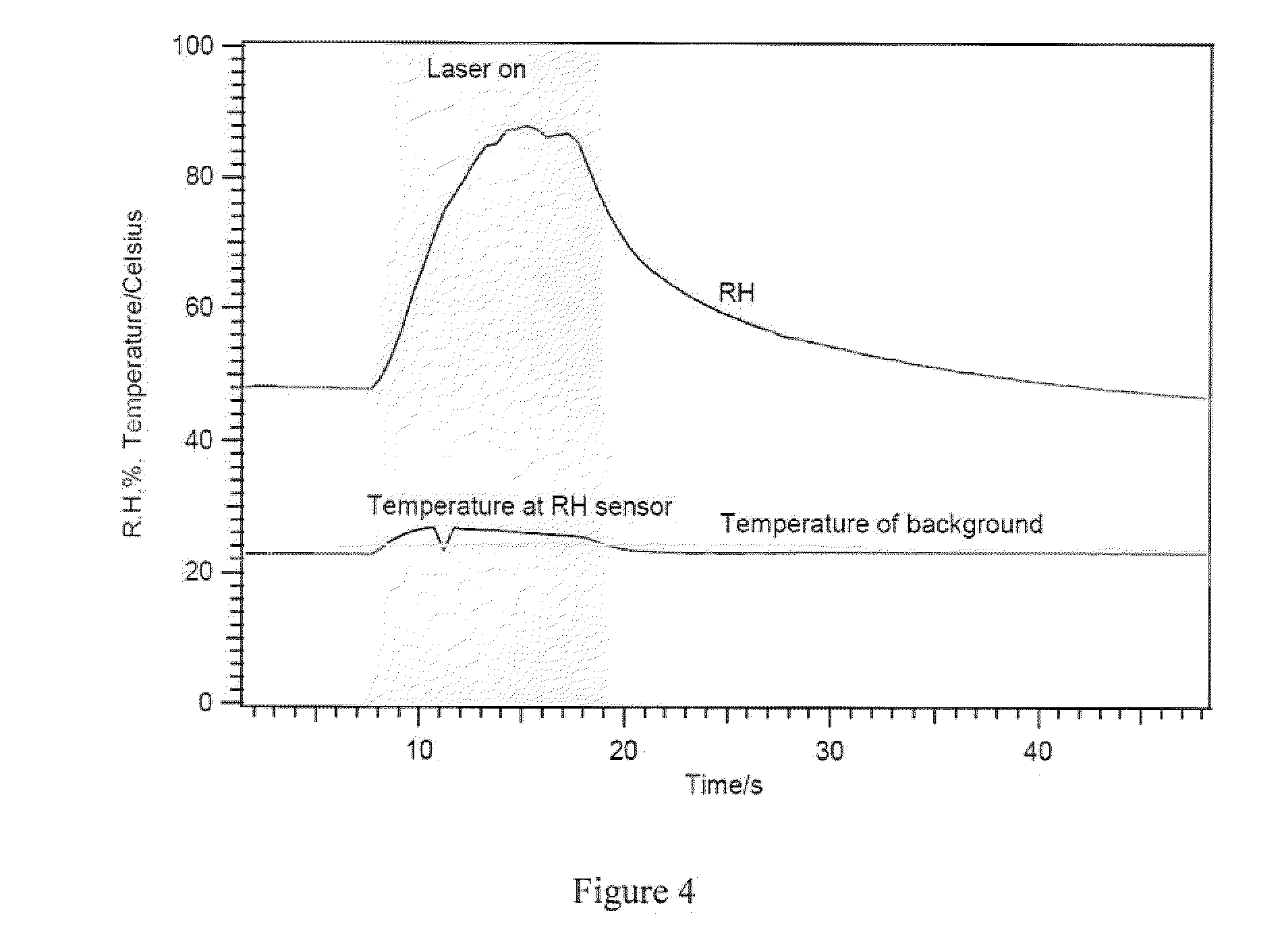
[0133]Each of these examples is based on the generation of hydrogen fluoride (HF). HF has an important property in that under standard temperature and pressure (STP), it condenses at 19.5° C. whereas the other hydrogen halides condense at much lower temperatures. The properties of the surrounding gas ambient are important to ensure that an intact liquid film of HF is generated and maintained for a significant time on the order of seconds to minutes.

[0134]The words “comprises / ...


PUM

PropertyMeasurementUnit
Angleaaaaaaaaaa
Temperatureaaaaaaaaaa
Flow rateaaaaaaaaaa

Abstract

The present invention relates to a method for laser ablation. The method comprises providing a substrate from which material is to be ablated and providing an ambient environment for the laser ablation process, comprising supplying a prescribed assist gas in a prescribed delivery configuration. The method further comprises focusing a laser beam onto the substrate to be ablated at a power density above an ablation threshold of the material to remove material from the substrate in a laser material interaction zone at or adjacent to the focal point of the laser; and controlling the supply of the assist gas and the laser power to generate a liquid phase in the laser material interaction zone in which the ablated matter is suspended.

Description

FIELD OF THE INVENTION[0001]The present invention relates to the generation and application of a liquid phase to enhance the process of laser ablation. Specifically the invention relates to a technique for enhanced entrainment, transport, containment and subsequent assembly of laser-ablated matter. At a scientific level the invention centres on laser-material-ambient interactions. In terms of applications the invention is relevant to micro- and nano-scale materials and process engineering.BACKGROUND TO THE INVENTION[0002]Laser ablation is the process of ejection of matter from a solid by irradiating it with a laser beam. At sufficiently high laser powers, the ejected matter can be further excited to a plasma phase. Processes based on laser ablation can be used to perform material removal operations, such as drilling, cutting, or etching, and material additive operations such as materials deposition, transfer or nanoparticle growth.[0003]Laser ablation produces particles directly by ...

Claims


Application Information

Patent Timeline
IPC IPC(8): C23F1/02B29B9/00B29C35/08B05D7/00
CPCB23K26/032B23K26/12B23K26/125B23K26/126B23K26/127B23K26/1405B23K26/1447B23K26/1452B23K26/36B23K26/14B23K26/142B23K26/1437B23K26/1438
Inventor CONNEELY, ALANHOWARD, HELENO'CONNOR, GERARDSEDAO,HAUSTRUP, NATALIE
Owner NATIONAL UNIVERSITY OF IRELAND
Why Eureka
Try Eureka