Grazing incidence collector for laser produced plasma sources
- Summary
- Abstract
- Description
- Claims
- Application Information
AI Technical Summary
Benefits of technology
Problems solved by technology
Method used
Image
Examples
Example
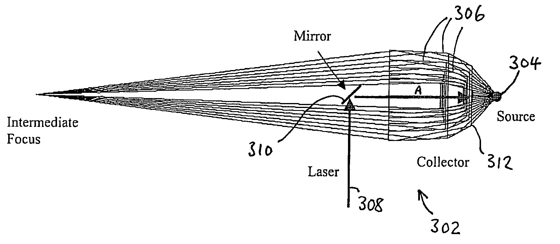
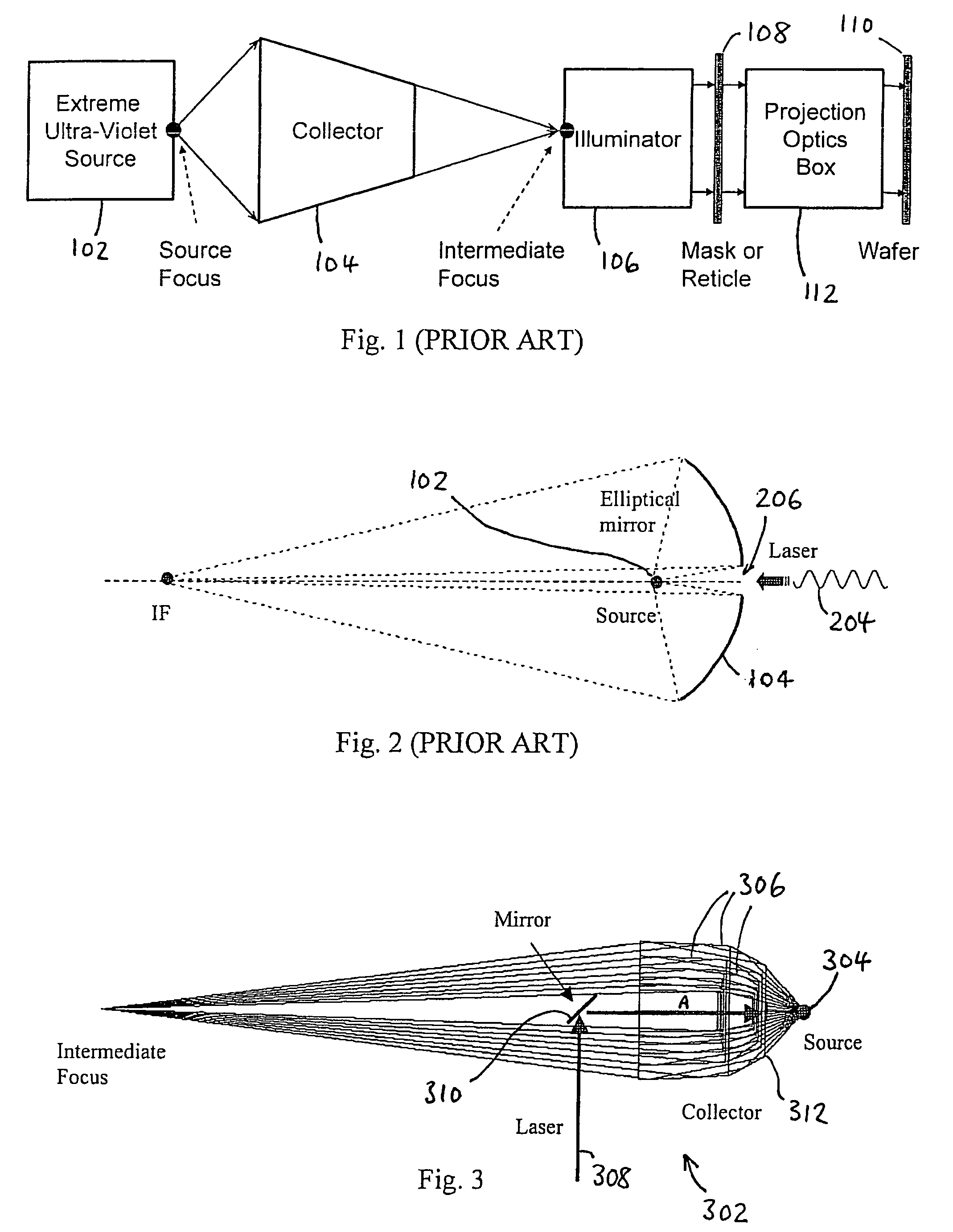
[0065]FIG. 3 shows a grazing incidence collector 302 according to a first embodiment of the invention, for use with a LPP source 304. The collector 302 consists of a plurality of concentrically aligned mirrors or shells 306; in this embodiment, there are six mirrors 306, as shown in FIG. 3; however, it will be appreciated that any suitable number of mirrors may be used. Each mirror 306 may have the same or different design, including, but not limited to, Wolter, elliptical, “equal reflection angle,” and “off-axis Wolter” designs. The design of such “equal reflection angle” grazing incidence collectors is discussed in, for example, European patent application no. 06425539.1 (attorney's ref. MLOOH19 / P-EP). The design of such “off-axis Wolter” grazing incidence collectors is discussed in, for example, European patent application no. 06425634.0 (attorney's ref. MLOOH21 / P-EP).
[0066]In this embodiment, the laser beam 308 propagates from the same side of the collector 302 as the IF, throug...
Example
[0093]FIG. 5 shows a grazing incidence collector according to a second embodiment of the invention. This is the same as the first embodiment, except as follows. In this embodiment, the laser beam 308 propagates initially from the side of the collector 302′ opposite the IF (i.e. in the direction of arrow B) and is reflected back and focused onto the fuel target (corresponding to source focus 304, and produced by fuel droplet generator 313) by means of a spherical mirror 314. The mirror 314 may be a cooled mirror. An exemplary consequent emitted / reflected EUV ray is indicated by 316.
Example
[0094]FIG. 6 shows a grazing incidence collector according to a third embodiment of the invention. This is the same as the first embodiment, except as follows. Again, laser beam 308 propagates initially from the side of the collector 302″ opposite the IF. It is focused by a large diameter lens 318, which therefore is subjected to lower laser pulse energy density. The beam 308 is then reflected back onto the fuel target fuel target (corresponding to source focus 304, and produced by fuel droplet generator 313) by means of a flat mirror 320. The mirror 320 may be a cooled mirror. An exemplary consequent emitted / reflected EUV ray is indicated by 316.
PUM
Abstract
Description
Claims
Application Information
- R&D Engineer
- R&D Manager
- IP Professional
- Industry Leading Data Capabilities
- Powerful AI technology
- Patent DNA Extraction
Browse by: Latest US Patents, China's latest patents, Technical Efficacy Thesaurus, Application Domain, Technology Topic.
© 2024 PatSnap. All rights reserved.Legal|Privacy policy|Modern Slavery Act Transparency Statement|Sitemap