System and method for entangled photons generation and measurement

a generation and measurement system, applied in the field of generation and measurement of quantum states of light, can solve the problems of difficult adjustment of polarization analyzer to the correct setting, difficult measurement of polarization entangled light, and inability to directly set polarization analyzer using entangled light, etc., to achieve speed up and simplify alignment procedure

Active Publication Date: 2010-12-09
NUCRYPT
View PDF13 Cites 33 Cited by
  • Summary
  • Abstract
  • Description
  • Claims
  • Application Information

AI Technical Summary

Benefits of technology

[0014]This invention describes various techniques which modify the prior art fiber based entangled photon source (EPS) designs to make them robust and practical, including being compatible with automated alignment of the source and subsequent measurement apparatus. Some of the techniques, including the use of an external light source for alignment of the downstream measurement apparatus, where said source can be an inexpensive broad-band source such as a super-luminescent light emitting diode or amplified spontaneous emission from an Erbium doped fiber amplifier, are generally applicable to various EPS architectures. The use of a broadband alignment source is both convenient and allows for the alignment of multiple signal / idler pairs using one alignment source. In some embodiments the alignment source can be used to generate multiple output alignment signals with different non-orthogonal polarizations. Such alignment signals allow the downstream measurement apparatuses to be aligned without requiring the use of coincidence counts as a feedback signal, thereby speeding up and simplifying the alignment procedure. The alignment light is configured so as to generate just one specific output polarization at a time, for instance by using a single alignment source with an external switch to choose between sending the alignment light to one of two different alignment injection ports, or by using multiple alignment sources connected to the multiple alignment source injection ports and turning them on and off as needed. In general all the alignment sources are turned off when an entangled light output is desired.
[0015]We also describe a method of monitoring the quality of the setting of the polarization controller inside Sagnac loop EPS architecture so that the polarization controller can be automatically controlled to the desired set-point. In some cases, polarization controllers are also located outside the interferometer containing the nonlinear fiber, and the methods used to set such polarization controllers are described. The polarization controllers can be set to aid in alignment, or to control the splitting ratio of the pump photons into the Sagnac loop so as to generate a particular entangled state, or generate a quantum correlated state. Alignment signals can be time-multiplexed with the entangled signal in order to allow for the settings of the detection system to be constantly monitored and improved as needed. A goal of this invention is to make the generation and subsequent measurement a straight-forward, reliable, and robust process.

Problems solved by technology

Polarization entangled light is sometimes difficult to measure because the polarization rotations that take place in the fiber connecting the entangled source to the measurement device need to be properly accounted for.
Adjusting the polarization analyzer to the correct setting becomes more difficult if the entangled light propagates through fiber—particularly if both the signal and idler propagate through different fibers as will generally be the case.
One can not easily set the polarization analyzer using the entangled light directly.
One can search for the settings that lead to the desired coincidence count performance, but this is difficult to do due to the dimensionality of the system and the fact that coincidence counts are relatively rare events.
However, in its original form the architecture requires the manual adjustment of an in-loop polarization controller and uses an undesirable amount of free-space optical components.

Method used


Image

  • System and method for entangled photons generation and measurement
  • System and method for entangled photons generation and measurement
  • System and method for entangled photons generation and measurement

Examples


Embodiment Construction

[0024]The foregoing description of a preferred embodiment of the invention has been presented for purposes of illustration and description. It is not intended to be exhaustive or to limit the invention to the precise forms disclosed. Obviously, many modifications and variations will be apparent to practitioners skilled in this art. It is intended that the scope of the invention be defined by the following claims and their equivalents.

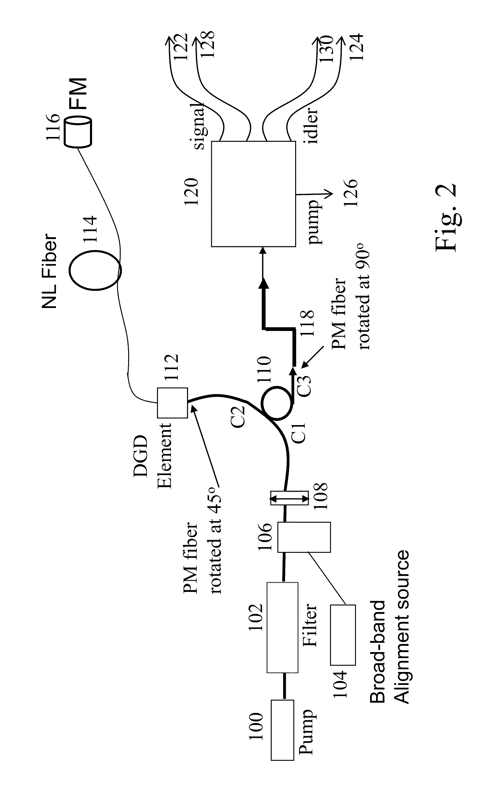
[0025]As one embodiment of the invention we consider a Michelson interferometer based entangled photon architecture as shown in FIG. 2. Pump laser pulses are generated in the pump laser 100 and filtered through a pump filter 102 to specify the optical bandwidth and reduce stray light. The pump light is combined with an alignment source 104 using a combiner 106, which could be a wavelength division multiplexer or a simple fiber coupler. Note that the alignment source is preferably a broad-band source of photons including photons in the signal and idler b...


PUM

PropertyMeasurementUnit
angleaaaaaaaaaa
angleaaaaaaaaaa
wavelengthsaaaaaaaaaa

Abstract

Apparatus and method for producing quantum entangled signal and idler photon pairs is provided. The apparatus makes use of a nonlinear optical fiber to generate the entangled photons. The use of an external broad band light source for alignment of any downstream measurement apparatuses is disclosed. One or more polarized output signals can be generated at both the signal and idler wavelengths using the alignment source, allowing the downstream measurement apparatuses to be aligned using classical light. Multiple signal and idler wavelengths can be generated and aligned using such a system.

Description

CROSS-REFERENCE TO RELATED APPLICATIONS[0001]The present invention claims the benefit of U.S. Ser. No. 61 / 153,363 filed Feb. 18, 2009 and is also a continuation-in-part of Ser. No. 12 / 372,213 filed Feb. 17, 2009 which is fully incorporated herein by reference.STATEMENT REGARDING FEDERALLY SPONSORED RESEARCH OR DEVELOPMENT[0002]The United States Government has certain rights to this invention pursuant to contract No. W911NF-08-C-0101 from the US Army Research Office.FIELD OF THE INVENTION[0003]The present invention relates to a method of generating and measuring quantum states of light called entangled photons or generating light beams that are quantum correlated. These states have various applications including quantum communication, metrology, and computing.BACKGROUND[0004]Entangled photon states are special quantum states of light which have been shown to be useful for various applications such as quantum key distribution and quantum metrology. This invention is related to the cre...

Claims


Application Information

Patent Timeline
Patent Type & Authority Applications(United States)
IPC IPC(8): G01J4/00G02F1/39
CPCH04B10/70H04B10/30
Inventor KANTER, GREGORY S.WANG, SHAWN
Owner NUCRYPT
Why Eureka
Try Eureka