
Gas absorption membranes and the manufacture thereof

a technology of gas absorption membrane and gas absorption membrane, which is applied in the direction of membranes, separation processes, membranes, etc., can solve the problem of the size of the column required for carbon dioxide extraction from the flue gas

Inactive Publication Date: 2010-12-16
CO2CRC TECH PTY LTD
View PDF11 Cites 22 Cited by
  • Summary
  • Abstract
  • Description
  • Claims
  • Application Information

AI Technical Summary

Benefits of technology

[0009]b) a thin coating on at least one side of the substrate such that the pores are substantially unobstructed by the coating, and when in use, the gas phase penetrates the pores of the substrate, and a liquid solvent in contact with the coating is substantially resisted from penetrating the pores, and wherein carbon dioxide in the pores of the substrate is transferred to the liquid solvent.
[0019]b) a thin hydrophobic coating on one side of the substrate in which the pores of the substrate are substantially unobstructed by the coating so that the non-aqueous phase can penetrate the pores, and the coating opposes or substantially resists the aqueous phase from penetrating the pores of the membrane from the side having the coating, and thereby facilitating transfer of the targeted substance between the aqueous and non-aqueous phases.

Problems solved by technology

One of the disadvantages of using a packed column for extracting carbon dioxide from the flue gas is the size of the column required.

Method used


Image

  • Gas absorption membranes and the manufacture thereof
  • Gas absorption membranes and the manufacture thereof
  • Gas absorption membranes and the manufacture thereof

Examples


example 1

[0061]This example involves a flat substrate of polypropylene being plasma treated to form a fluorinated coating which is hereinafter referred to as the treated polypropylene membrane or PTPP. The PTPP is manufactured and compared for mass transfer performance with untreated polypropylene (PP) and polytetrafluoroethylene (PTFE).

[0062]Scanning electron microscopy (SEM) images of the membranes were captured and the surface morphology analysed to calculate surface porosity, average pore size and thickness. An image analysis program, namely Version 1.24 by ImageJ was used to calculate the surface porosity. A summary of the properties of the PP, PTPP and PTFE membranes is provided in Table 1 below.

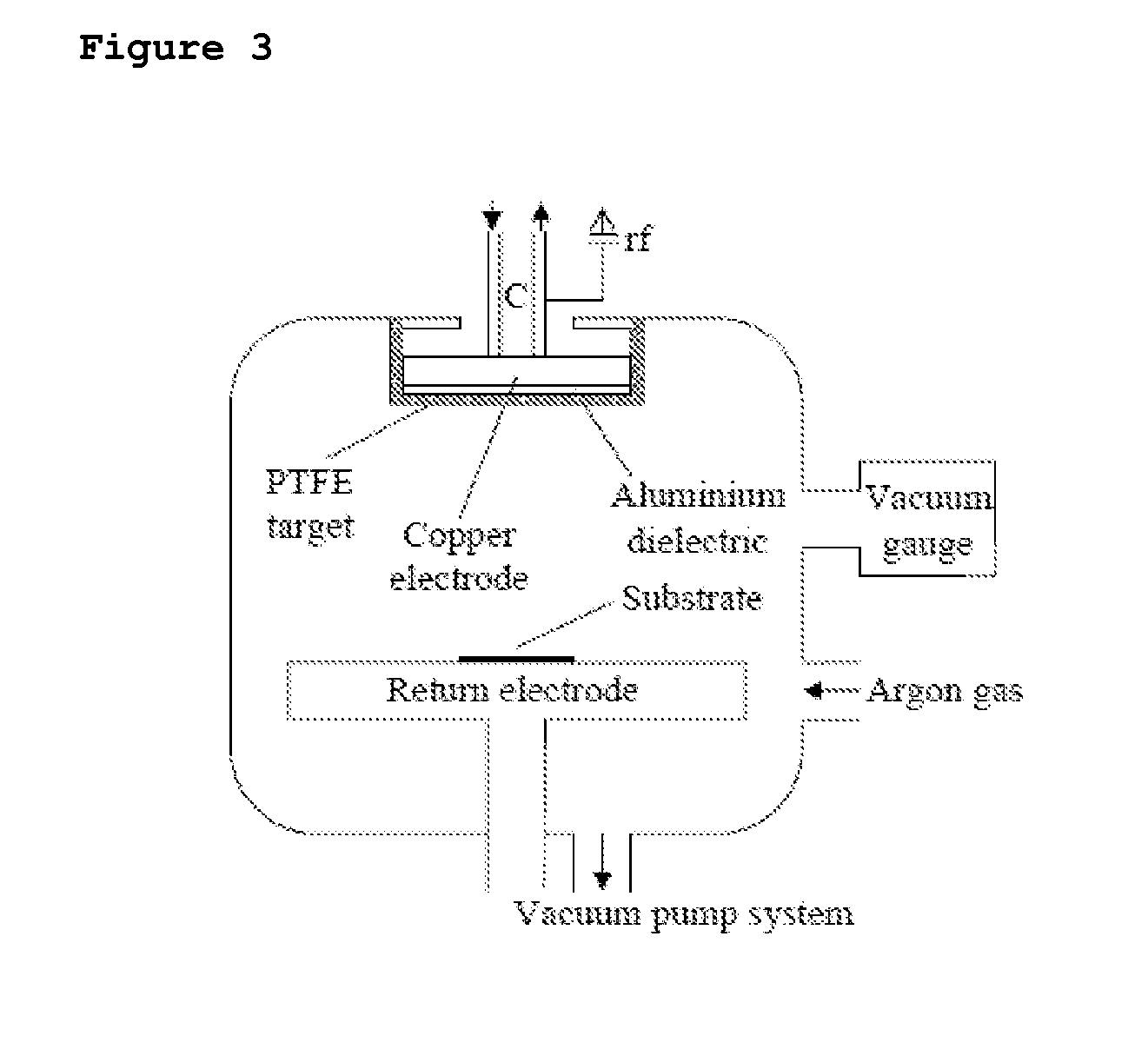
[0063]A sample of the PP membrane was plasma treated to form a fluorinated coating on one side of the PP. The apparatus and method for treating the PP membrane is schematically illustrated in FIG. 3. The apparatus includes a reaction chamber that is capacitatively coupled to a radio-frequency g...

example 2

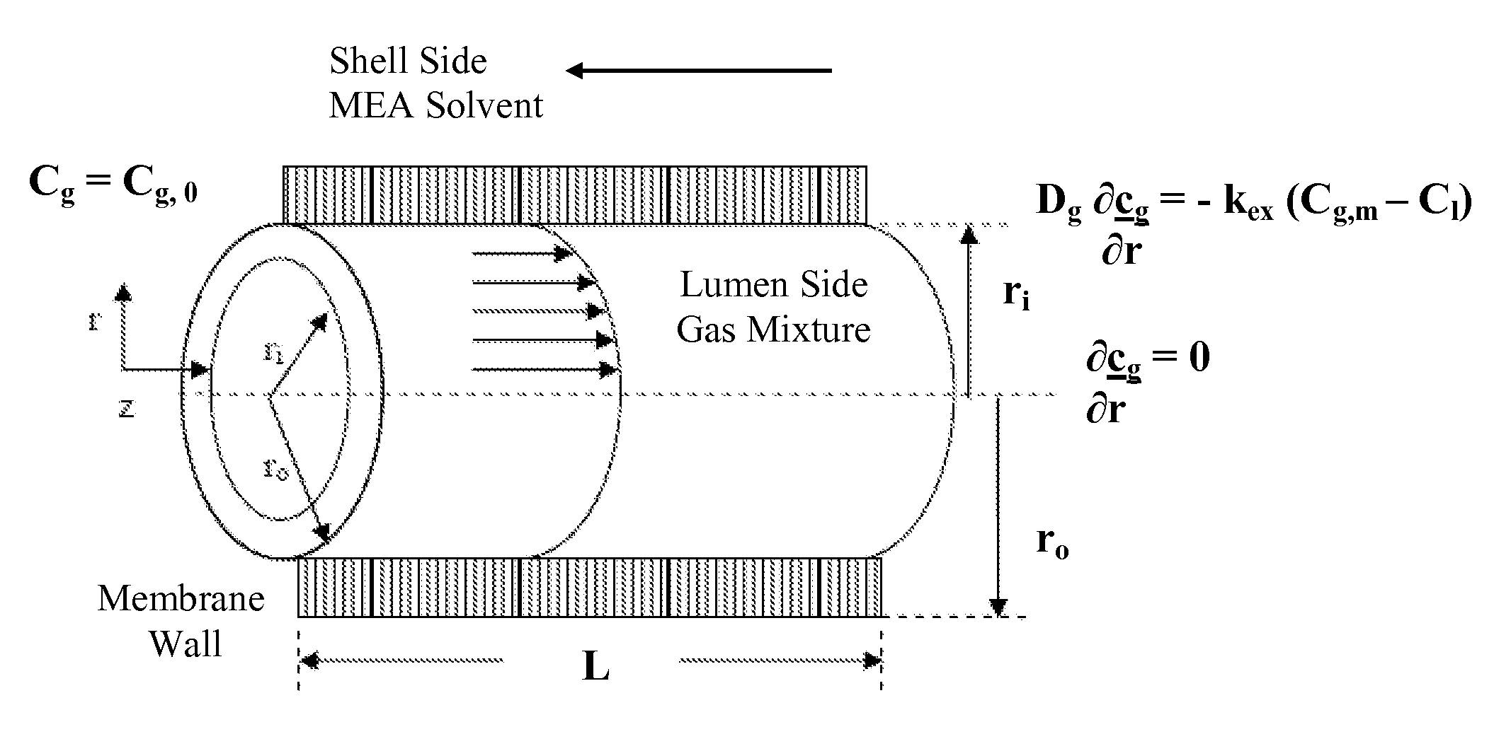
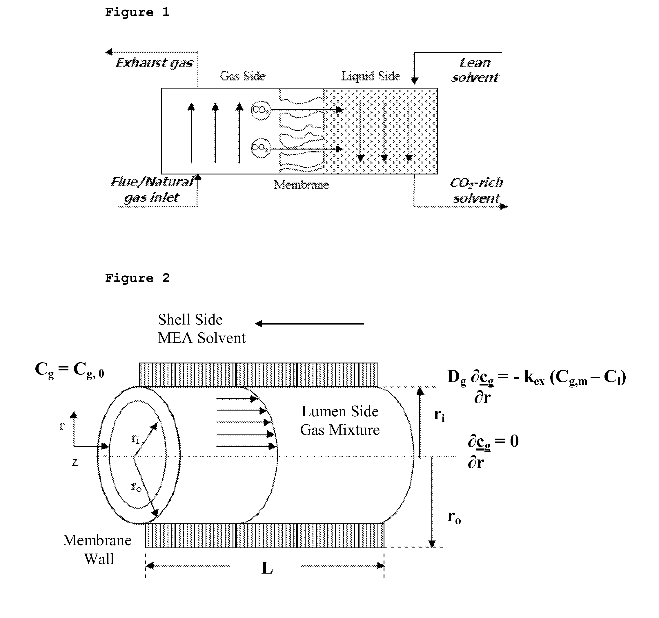
[0098]The procedure as outline above was again repeated in respect of the hollow tubular or hollow fibre PP membranes that provided “a control”, PTFE hollow fibres that represent that ideal situation and plasma treated polypropylene or PTPP hollow fibres that are the subject of the present invention. FIG. 2 is a representation of a single hollow fibre. Again a scanning electron microscope (SEM) and X-ray photoelectron spectroscopy (XPS) was conducted to determine physical properties and composition of the membranes.

[0099]Table 7 below is a summary of the physical properties of the membranes.

TABLE 7Polymer TypePPPTFEPlasma Treated PPFibre ManufacturerMemtec,SumitomoMemtec, AustraliaAustraliaElectric(treated in house)Fine Polymer,JapanFibre ID / OD (mm)0.3 / 0.671 / 20.3 / 0.67No. of fibres50027500Contactor Length (cm)12.711.012.7Mass Transfer Area,598 / 1337 93 / 187598 / 1337based on ID / OD (cm2)Membrane contactor718671void fraction (%)

[0100]A series of hollow fibre membrane cartridges were constr...


PUM

PropertyMeasurementUnit
thicknessaaaaaaaaaa
breakthrough pressureaaaaaaaaaa
porosityaaaaaaaaaa

Abstract

A membrane is used for separating carbon dioxide from a gas phase. The membrane includes a substrate having micro-pores that extend through the substrate and a thin hydrophobic coating on one side of the substrate in which the pores of the substrate are substantially unobstructed by the coating so that the gas phase can penetrate the pores. The coating opposes or substantially resists a liquid solvent for absorbing carbon dioxide from penetrating the pores of the membrane from the side having the coating. The membrane may also be used for separating carbon dioxide in a flue gas of a coal fired power station. Further, the coating may be relatively inert to the liquid solvent compared to the substrate.

Description

FIELD OF THE PRESENT INVENTION[0001]The present invention relates to gas absorption membranes for separating carbon dioxide from gas streams such as flue gas streams of coal fired power stations and a process for the manufacture of the membranes. The gas absorption membranes may have a broad range of applications such as, but by no means limited to, separating carbon dioxide from natural gas and processing streams of cement, iron and other metal refining plants.BACKGROUND OF THE PRESENT INVENTION[0002]The current technology which exists to separate carbon dioxide from flue gas involves chemical absorption in a packed column using an amine based solvent. The technology has been used in industry for over 50 years and has a number of disadvantages. One of the disadvantages of using a packed column for extracting carbon dioxide from the flue gas is the size of the column required. For instance, a typical 645MW coal fired power station produces a flue gas at a rate of 2×10⁶ m3 / hr and con...

Claims


Application Information

Patent Timeline
Patent Type & Authority Applications(United States)
IPC IPC(8): B01D53/14C23C14/34B01D53/22
CPCB01D53/228B01D53/229B01D61/00B01D67/0004B01D69/02B01D69/04B01D69/127B01D71/26B01D71/32B01D71/36B01D2257/504B01D2258/06B01D2325/06B01D2325/38Y02C10/06Y02C10/10Y02C20/40
Inventor STEVENS, GEOFFPERERA, JILSKAFRANCO, JULIANNAKENTISH, SANDRA
Owner CO2CRC TECH PTY LTD
Learn More