Front end scribing of light emitting diode (LED) wafers and resulting devices

Active Publication Date: 2010-12-16
CREELED INC
View PDF12 Cites 26 Cited by
  • Summary
  • Abstract
  • Description
  • Claims
  • Application Information

AI Technical Summary

Benefits of technology

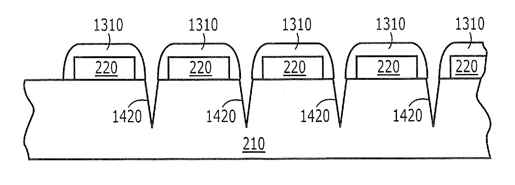
[0016]Moreover, the oblique sidewall of the crystalline substrate also may include texturing therein that extends along crystal planes of the crystalline substrate. This texturin

Problems solved by technology

However, since many of the substrate wafers are extremely hard, the use of mechanical scribing

Method used


Image

  • Front end scribing of light emitting diode (LED) wafers and resulting devices
  • Front end scribing of light emitting diode (LED) wafers and resulting devices
  • Front end scribing of light emitting diode (LED) wafers and resulting devices

Examples


Embodiment Construction

[0028]The present invention now will be described more fully with reference to the accompanying drawings, in which various embodiments are shown. This invention may, however, be embodied in many different forms and should not be construed as limited to the embodiments set forth herein. Rather, these embodiments are provided so that this disclosure will be thorough and complete, and will fully convey the scope of the invention to those skilled in the art. In the drawings, the size and relative sizes of layers and regions may be exaggerated for clarity. Like numbers refer to like elements throughout.

[0029]It will be understood that when an element such as a layer, region or substrate is referred to as being “on” another element, it can be directly on the other element or intervening elements may also be present. Furthermore, relative terms such as “beneath” or “overlies” may be used herein to describe a relationship of one layer or region to another layer or region relative to a subst...


PUM


Abstract

A wafer of light emitting diodes (LEDs) is laser scribed to produce a laser scribing cut. Then, the wafer is cleaned, for example by wet etching, to reduce scribe damage. Then, electrical contact layers for the LEDs are formed on the wafer that has been cleaned. Alternatively, the scribing cut may be produced by multiple etches before contact formation. Related LEDs are also described.

Description

BACKGROUND OF THE INVENTION[0001]This invention relates to methods of fabricating semiconductor light emitting devices and resulting structures, and more particularly to methods of fabricating semiconductor Light Emitting Diodes (LEDs) and resulting structures.[0002]Semiconductor LEDs are widely known solid-state lighting elements that are capable of generating light upon application of voltage thereto. LEDs generally include a diode region including therein an n-type layer, p-type layer and a p-n junction. An anode contact ohmically contacts the p-type layer and a cathode contact ohmically contacts the n-type layer.[0003]LEDs generally are fabricated in wafer form, wherein an epitaxial region, including the diode region, is epitaxially formed on a substrate, such as a sapphire, silicon, silicon carbide, gallium arsenide, gallium nitride, etc. growth substrate. The diode region may be fabricated, for example, from silicon carbide, gallium nitride, gallium phosphide, aluminum nitride...

Claims


Application Information

Patent Timeline
IPC IPC(8): H01L21/78H01L33/00H01L21/268
CPCH01L33/0079H01L33/0095H01L33/22H01L33/0093H01L33/00
Inventor DONOFRIO, MATTHEWPARKER, WINSTON T.BERGMANN, MICHAEL JOHNGILMORE, STEVEN SCOTTNORMAN, JAY THOMASSCHNEIDER, KEVIN SHAWNE
Owner CREELED INC
Why Eureka
Try Eureka