Swash plate of a swash plate type compressor and the swash plate type compressor

a compressor and swash plate technology, applied in the direction of oblique crank gearings, positive displacement liquid engines, gearings, etc., can solve the problems of reducing the flatness of the swash plate, forming a metal spray coating layer of copper, etc., and achieve good surface flatness and uniform thickness. , good surface flatness

Inactive Publication Date: 2010-12-16
NTN CORP
View PDF16 Cites 8 Cited by
  • Summary
  • Abstract
  • Description
  • Claims
  • Application Information

AI Technical Summary

Benefits of technology

[0034]Because the substrate of the swash plate used in the swash plate type compressor according to the present invention comprises a disk-shaped steel sheet formed by pressing a rolled steel sheet into a disk shape, and both surfaces of the disk-shaped steel sheet is ground, its surface flatness is good, and the coating film forming the low-friction resin coating layers can be strongly fixed to the substrate without the need to form a metal spray coating layer on the surface of the substrate. Thus, the low-friction resin coating layers are less likely to peel off.
[0035]Since the substrate of the swash plate has a good surface flatness, the low-friction resin coating layers can maintain uniform thickness, which ensures stable boundary lubricating condition by lubricating oil, and also ensures stable friction / wear properties in the boundary lubricating condition even if lubricating oil runs out.
[0036]Since the swash plate type compressor according to this invention includes the above-described swash plate, it shows sufficient durability even if carbon dioxide gas is used as a refrigerant, of which the pressure in the compressor reaches as high as 10 MPa.

Problems solved by technology

As stated above, it is costly to form a metal spray coating layer of a copper type or aluminum type material on the surface of the substrate as an intermediate layer.
Also, such a metal spray coating layer tends to lower the flatness of the swash plate.

Method used


Image

  • Swash plate of a swash plate type compressor and the swash plate type compressor
  • Swash plate of a swash plate type compressor and the swash plate type compressor
  • Swash plate of a swash plate type compressor and the swash plate type compressor

Examples


examples

Examples of the Invention

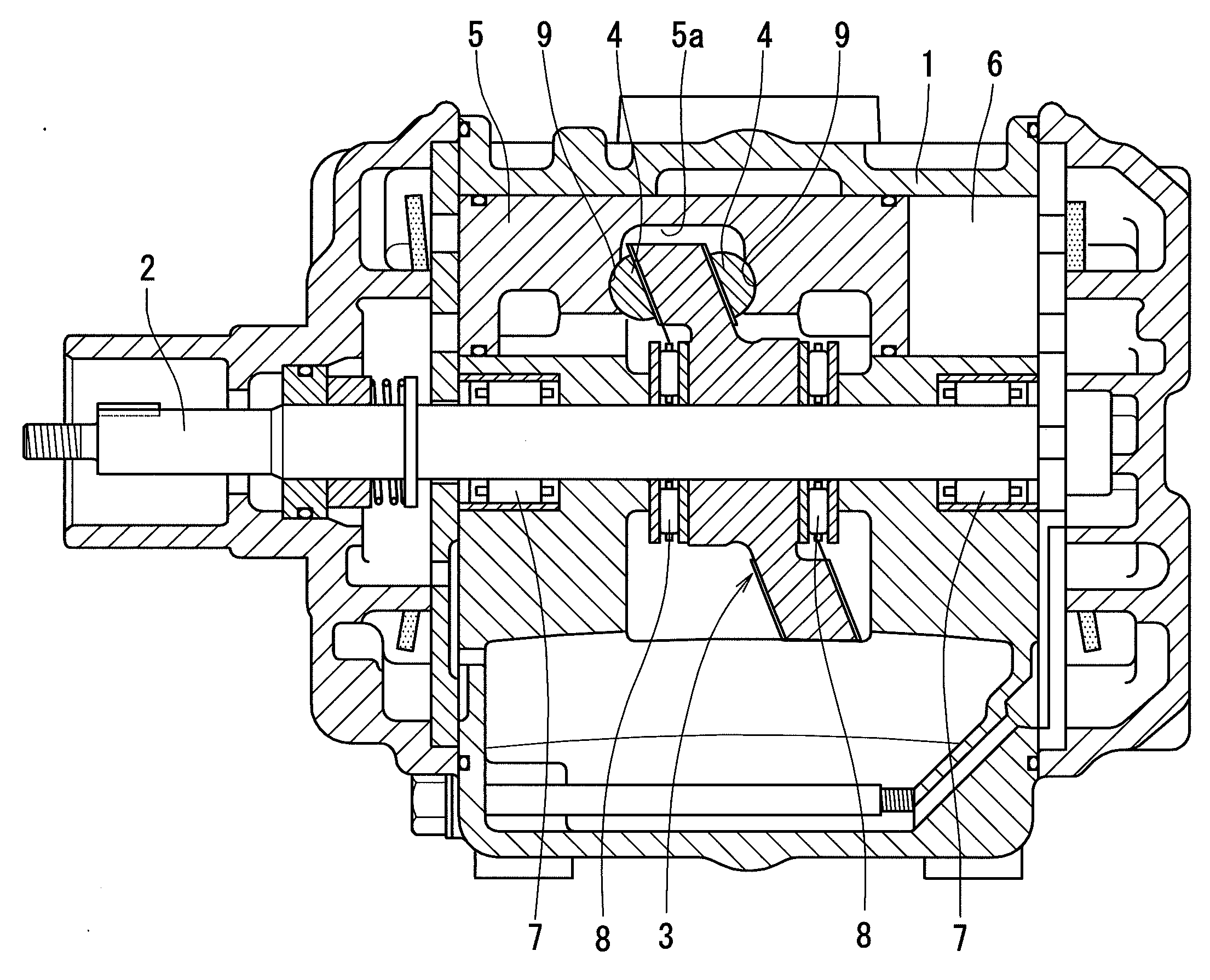
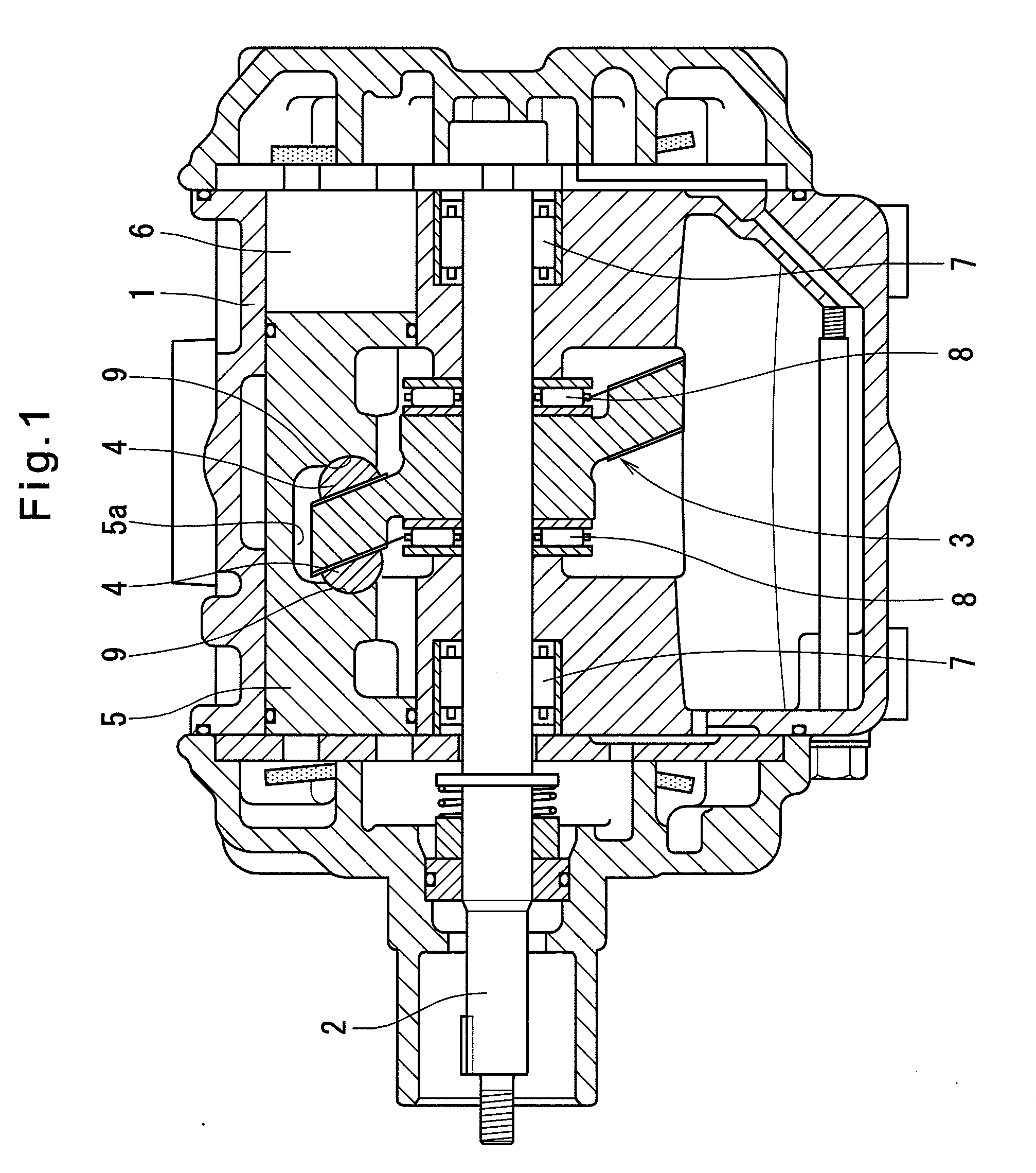
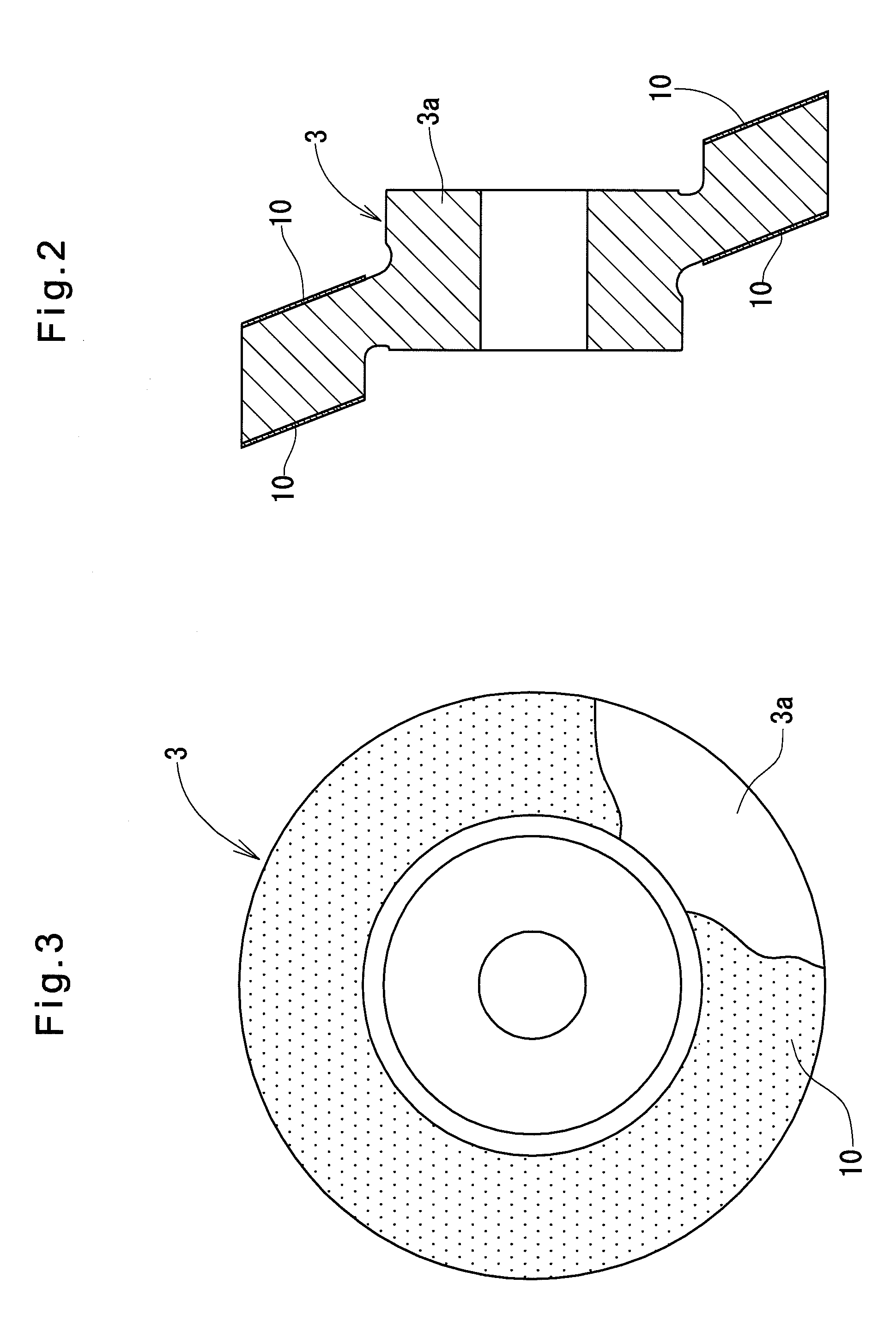
[0057]In each example of the invention, the substrate 3a of the swash plate 3 was formed as follows: A steel sheet SAPH440C was formed into a disk shape by pressing, and roughly machined by a lathe to the thickness of 6.5 mm and a diameter of 90 mm. Both sides thereof were then ground using a two-head grinding machine (grinder: #80) so that the thickness of the substrate decreases to 6.36 mm. Table 1 shows the measured accuracy values after the respective steps.

[0058]The disk substrates thus formed were subjected to shot blasting to increase their surface roughness.

[0059]Then, a low-friction resin coating composition containing formula A as solid contents were applied by spray coating to both sides of the respective specimens thus formed so that their thicknesses are 30 μm on both sides after baking. After baking, final finish machining was carried out using a two-head grinding machine (grinder: #400 for resin) (to the thickness of 6.40 mm). Measured accurac...


PUM

PropertyMeasurementUnit
thicknessaaaaaaaaaa
particle diameteraaaaaaaaaa
flatnessaaaaaaaaaa

Abstract

The object of the present invention is to provide a swash plate which fulfils the basic properties required for a swash plate, which are stable boundary lubricating state by lubricating oil, without forming a metal spray coating layer comprising a copper type or aluminum type material on the surface of the substrate 3a forming the swash plate 3 of the swash plate type compressor as an intermediate layer.The substrate 3a of the swash plate 3 comprises a disk-shaped steel sheet formed by pressing a rolled steel sheet into a disk shape, and both surfaces of the disk-shaped steel sheet is ground. Thus, resin coating layers 10 containing fluororesin, which has superior seizure resistance, can be strongly fixed to the substrate without the need to form a metal spray coating layer on the surface of the substrate. This improves the durability of the swash plate type compressor using carbon dioxide gas as a refrigerant.

Description

TECHNICAL FIELD[0001]The present invention relates to a swash plate of a swash plate type compressor used e.g. in an air-conditioner, and the swash plate type compressor.BACKGROUND ART[0002]A swash plate type compressor includes a swash plate mounted directly to a rotary shaft or indirectly to the rotary shaft through a coupling member so as to be oblique to or perpendicular to the rotary shaft in a housing in which a refrigerant exists, the swash plate being in sliding contact with shoes such that the rotary motion of the swash plate is converted to reciprocating motion of pistons through the shoes, thereby compressing and expanding the refrigerant. There are two types of such swash plate type compressors, one including two-head pistons and adapted to compressing and expanding the refrigerant on both sides of the pistons, and one including single-head pistons and adapted to compress and expand the refrigerant on one side only of the pistons. The shoes of some of swash plate type co...

Claims


Application Information

Patent Timeline
Patent Type & Authority Applications(United States)
IPC IPC(8): F04B19/00F16H23/00
CPCF04B27/1054F05C2225/00F05C2253/12F05C2253/20B23P15/00F01B3/02Y10T29/49236F04B1/146B05D2350/38B05D5/083Y10T74/18336F04B25/04F04B27/0821F04B39/00
Inventor TANIGAWA, NAONARIOKI, YOSHIO
Owner NTN CORP
Why Eureka
Try Eureka