Sputtering Target of Nonmagnetic-Particle-Dispersed Ferromagnetic Material

a ferromagnetic material and non-magnetic particle technology, applied in the direction of diaphragms, metallic material coating processes, conductive materials, etc., can solve the problems of large power consumption, inferior sputtering efficiency, high cost of rf (radio frequency) sputtering devices, etc., to achieve easy control, increase deposition speed, and improve the effect of

Active Publication Date: 2010-12-23
JX NIPPON MINING& METALS CORP
View PDF12 Cites 27 Cited by
  • Summary
  • Abstract
  • Description
  • Claims
  • Application Information

AI Technical Summary

Benefits of technology

[0039]As described above, the adjusted target becomes a high PTF (pass through flux) target and, when using it with the DC magnetron sputtering system, this target exhibits superior effects that ionization of inert gas resulted from the cycloidal motion of the charged particles efficiently progresses and the deposition speed can be increased thereby.
[0040]Thus, high-speed deposition based on DC sputtering is enabled without increasing the pressure of the sputtering gas or the applied voltage. Moreover, in comparison to an RF sputtering system, the DC sputtering system is advantageous in that it is inexpensive and easy to control, and has low power consumption. Therefore, by using th

Problems solved by technology

Nevertheless, not only is the RF (radio frequency) sputtering device expensive, it possesses numerous drawbacks such as inferior sputtering efficiency, large power consumption, complex control and slow deposition speed.
If high power is applied to increase the deposition speed, the substrate temperature will rise, and there is a problem in that this will cause deterioration in the substrate and deposition material.
Even if the target possesses conductive property, such target that contains large amounts of nonconductive materials such as oxide and silicide makes deposition based on the DC sputtering method difficult since the bulk resistance of the target will increase.
Nevertheless, ev

Method used


Image

  • Sputtering Target of Nonmagnetic-Particle-Dispersed Ferromagnetic Material
  • Sputtering Target of Nonmagnetic-Particle-Dispersed Ferromagnetic Material
  • Sputtering Target of Nonmagnetic-Particle-Dispersed Ferromagnetic Material

Examples


examples

[0087]The present invention is now explained in detail with reference to the Examples and Comparative Examples. These Examples are merely illustrative, and the present invention shall in no way be limited thereby. In other words, various modifications and other embodiments based on the technical spirit claimed in the claims shall be included in the present invention as a matter of course.

examples 1 and 2

, and Comparative Examples 1 and 2

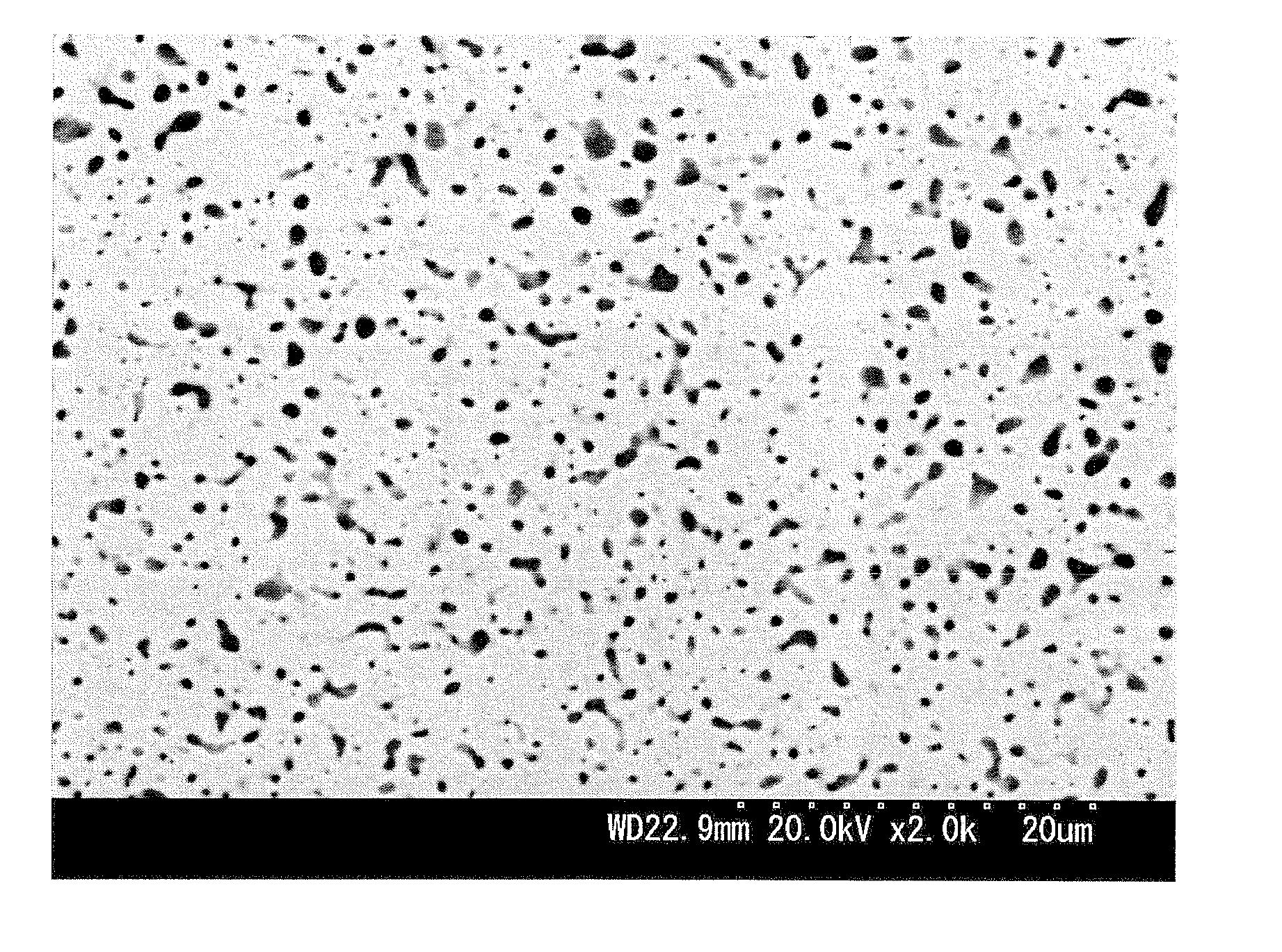
[0088]As sintering raw powder, Co—Cr alloy powder that was sorted with sieves having different sized sieve mesh, and fine powder (average grain size of 1 to 2 μm) of Co and silicon oxide (SiO2) are used.

[0089]In Example 1, Co—Cr alloy powder of 75 μm or larger and less than 150 μm was used, and in Example 2, Co—Cr alloy powder of 20 μm or larger and less than 75 μm was used.

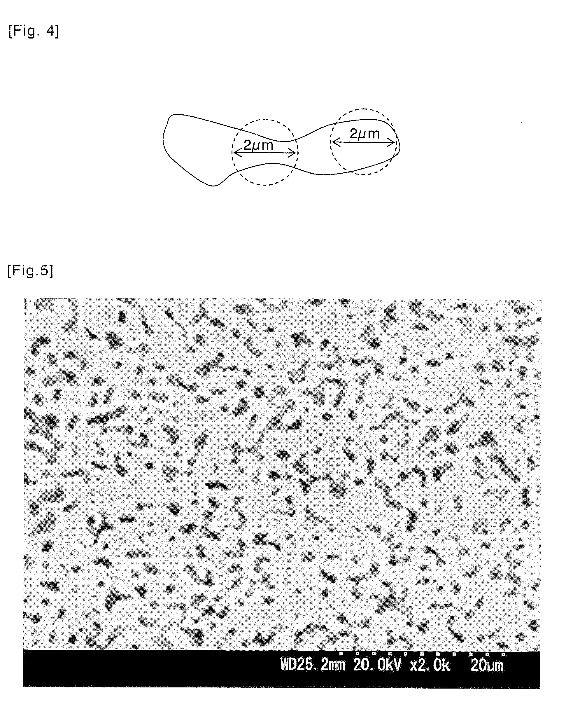
[0090]Moreover, in Comparative Example 1, Co—Cr alloy powder of less than 20 μm was used, and in Comparative Example 2, Co—Cr alloy powder was not used and Cr powder of less than 20 μm was used.

[0091]The Co—Cr alloy powder that was used herein is of a composition containing Cr at 40 at % or more.

[0092]The foregoing powders were weighed to achieve a composition of 77.28Co-14.72Cr-8SiO2 (mol %), and mixed in a wet ball mill for 20 hours. Subsequently, after the mixed powder was filled in a carbon mold and sintered with the hot press (HP) at 1050° C. for 2 hours, it was further subj...


PUM

PropertyMeasurementUnit
Lengthaaaaaaaaaa
Lengthaaaaaaaaaa
Lengthaaaaaaaaaa

Abstract

Provided is a sputtering target of nonmagnetic-particle-dispersed ferromagnetic material comprising a phase (A) such that nonmagnetic particles are dispersed in a ferromagnetic material formed from a Co—Cr alloy containing 5 at % or more and 20 at % or less of Cr and Co as the remainder thereof, and schistose textures (B) with a short side of 30 to 100 μm and a long side of 50 to 300 μm formed from a Co—Cr alloy phase in the phase (A); wherein each of the foregoing nonmagnetic particles has such a shape and size that the particle is smaller than all hypothetical circles with a radius of 1 μm around an arbitrary point within the nonmagnetic particle, or a shape and size with at least two contact points or intersection points between the respective hypothetical circles and the interface of the ferromagnetic material and the nonmagnetic material. Consequently, obtained is a high-density sputtering target of nonmagnetic-particle-dispersed ferromagnetic material whose crystal grains are fine, which realizes improvement of PTF (pass through flux) of the target, high-speed deposition with a magnetron DC sputtering system, reduction in the particles (dust) and nodules generated during the sputtering process, minimal variation in quality, and improvement of mass productivity.

Description

TECHNICAL FIELD[0001]The present invention relates to a sputtering target of nonmagnetic-particle-dispersed ferromagnetic material, and in particular relates to a target that can be efficiently subjected to sputtering with a DC (direct current) magnetron sputtering system by improving the PTF (pass through flux). The present invention further relates to a sputtering target of nonmagnetic-particle-dispersed ferromagnetic material which realizes stable sputtering and optimal deposition speed when forming a film by sputtering, minimal arcing during the sputtering, reduction in the particles (dust) and nodules caused by such arcing, high density, minimal variation in quality, and improvement of mass productivity.BACKGROUND ART[0002]In the field of magnetic recording, technology has been developed for improving the magnetic property by causing a nonmagnetic material to coexist in a magnetic thin film. As examples, there are technology for improving the soft magnetic property such as magn...

Claims


Application Information

Patent Timeline
IPC IPC(8): C23C14/34
CPCC22C19/07C22C49/08C22C49/14H01F41/183C23C14/3414G11B5/851C22C2202/02
Inventor SATO, ATSUSHI
Owner JX NIPPON MINING& METALS CORP
Why Eureka
Try Eureka