Method and Apparatus for Increased Current Stability in a PWM Drive

a technology of current stability and pwm, which is applied in the direction of motor/generator/converter stopper, pulse technique, dynamo-electric converter control, etc., can solve the problems of loss of control of the motor, loss of motor control, and digital nature of the motor drive, and may present further challenges for providing high-performance motor control

Active Publication Date: 2010-12-23
ROCKWELL AUTOMATION TECH
View PDF11 Cites 24 Cited by
  • Summary
  • Abstract
  • Description
  • Claims
  • Application Information

AI Technical Summary

Benefits of technology

[0007]The present invention provides an improved current regulator for PWM based drives for electric motors. The invention provides compensation for the rotor position signal for delays introduced due to the PWM algorithm and for digital sampling present in such a drive. Current regulators commonly operate in a two-phase reference frame and, preferably, the synchronous reference frame. Operating in the synchronous reference frame requires forward and reverse coordinate transformations between the measured current values in a stationary frame and the synchronous reference frame variables. The rotor position information is one of the variables used to perform this transformation. The present invention provides an improved compensation in the forward transformation, from a synchronous to a stationary reference frame, by accurately determining the phase lag between the commanded voltage reference and the output voltage reference and by further compensating the forward transformation for errors introduced due to sampling the current either at different sampling instances than the rotor position or at multiple sampling instances during a carrier period. Additionally, compensation during the reverse transformation, from the stationary to a synchronous reference frame, is provided to compensate for errors introduced due to the timing of sampling the current and rotor position signals.
[0011]Thus it is another feature of this invention that the compensated rotor position is used by the current regulator to improve stability of the current regulator.
[0015]Thus, it is another feature of this invention that the stability of the current regulator is enhanced by compensating the rotor position angle as a function of when the current is sampled during each carrier period prior to performing the current transformation.
[0019]Thus, it is another feature of this invention that the angle compensation in the current regulator provides increased stability of the control system, such that the drive may operate with a carrier frequency of the PWM algorithm close to the fundamental electrical frequency of the motor.

Problems solved by technology

However, PWM switching is not without drawbacks.
The stepped output voltage may produce undesirable operation, including instability of the current regulator resulting in a loss of control of the motor.
In addition to the potential instability in the current regulator, the digital nature of the motor drive may present further challenges for providing high performance motor control.
Such a delay results in the current regulator providing a voltage reference for the middle of the next carrier period as this is the period during which the reference is being applied to the motor.
While such compensation yields some improved performance, it fails to consider the dependency of the phase lag on the desired output frequency and on the timing of sampling the continuous time signals.

Method used


Image

  • Method and Apparatus for Increased Current Stability in a PWM Drive
  • Method and Apparatus for Increased Current Stability in a PWM Drive
  • Method and Apparatus for Increased Current Stability in a PWM Drive

Examples


Embodiment Construction

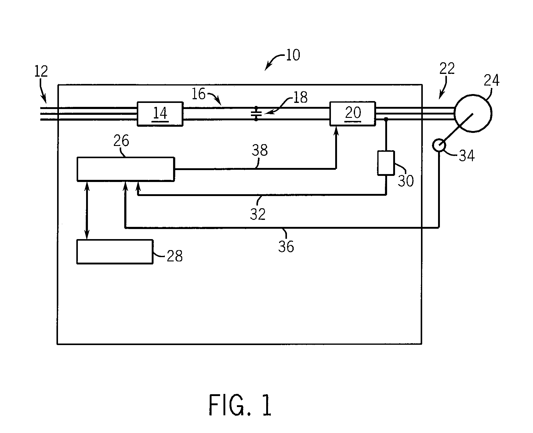
[0029]Referring now to FIG. 1, a motor drive 10 generally includes an input power source 12, such as a three-phase alternating current (AC) source. Alternately, the input power 12 could be a single-phase AC or direct current (DC) source. A preferred topology for the motor drive includes an input power source 12 connected to a rectifier section 14. The rectifier section 14 may be either active or passive, as is known in the art. The rectifier section 14 converts the input power 12 to a suitable DC voltage and supplies it to the DC bus 16. A DC bus capacitor 18 is connected between the positive and negative rails of the DC bus 16 to help maintain a substantially constant DC voltage level on the DC bus 16. The DC bus 16 is connected to an inverter section 20 which converts the DC bus voltage to an output voltage 22 suitable for use by the motor 24 connected to the motor drive 10.

[0030]Alternately, any suitable topology for a motor drive 10, including but not limited to a matrix convert...


PUM


Abstract

The present invention provides an improved current regulator for PWM based drives for electric motors. The invention provides compensation for the rotor position signal for delays introduced due to the PWM algorithm and for digital sampling present in such a drive. Current regulator commonly operate in a two-phase reference frame, requiring forward and reverse coordinate transformations between the physical current values and the two-phase reference frame variables. The present invention provides an improved compensation in the forward transformation by determining the phase lag between the commanded voltage reference and the output voltage reference and by further compensating the forward transformation for errors introduced due to sampling the current either at different sampling instances than the rotor position or at multiple sampling instances during a carrier period. Additionally, compensation during the reverse transformation is provided to compensate for errors introduced due to sampling the current and rotor position.

Description

BACKGROUND OF THE INVENTION[0001]The subject matter disclosed herein relates to power converters for electric motors. More specifically, the subject matter relates to a current regulator which compensates the rotor position signal for delays introduced due to pulse width modulation and digital sampling in a motor drive.[0002]As is known to those skilled in the art, electric motors require power converters, commonly called motor drives, to regulate the amplitude and frequency of the electrical voltage applied to the motor in order to achieve variable speed control of the motor. Motor drives commonly utilize Pulse Width Modulation (PWM) algorithms to vary the amplitude and frequency of the electrical voltage. These PWM algorithms operate to continuously switch a voltage, commonly a DC voltage, on and off. If analyzed over a short period of time, the switched output voltage results in an average voltage value applied to the motor. The motor drive uses a current regulator to generate a ...

Claims


Application Information

Patent Timeline
Patent Type & Authority Applications(United States)
IPC IPC(8): H03K5/00
CPCH03K17/14H02P21/00
Inventor ROYAK, SEMYONHARBAUGH, MARK M.NONDAHL, THOMAS A.LIU, JINGBOSCHMIDT, PETER B.BREITZMANN, ROBERT J.
Owner ROCKWELL AUTOMATION TECH
Why Eureka
Try Eureka