
Apparatus for Separating Pitch from Slurry Hydrocracked Vacuum Gas Oil

Active Publication Date: 2010-12-30
UOP LLC
View PDF54 Cites 26 Cited by
  • Summary
  • Abstract
  • Description
  • Claims
  • Application Information

AI Technical Summary

Benefits of technology

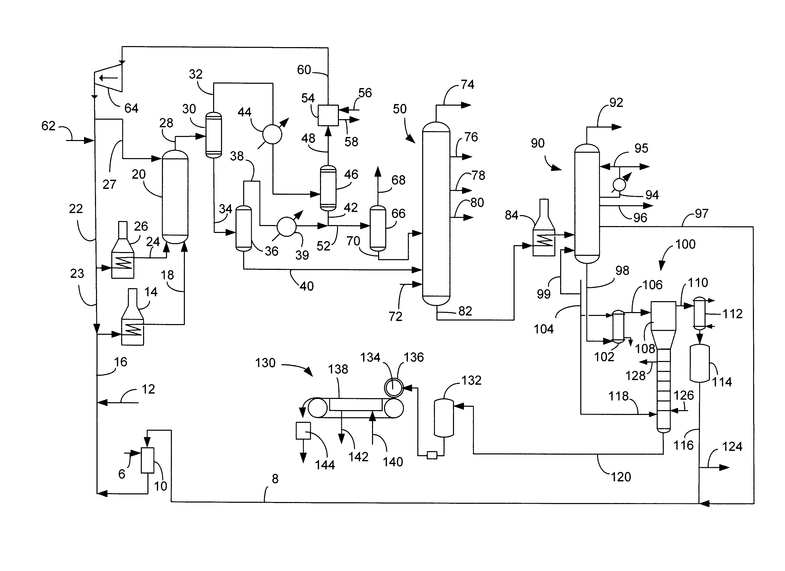
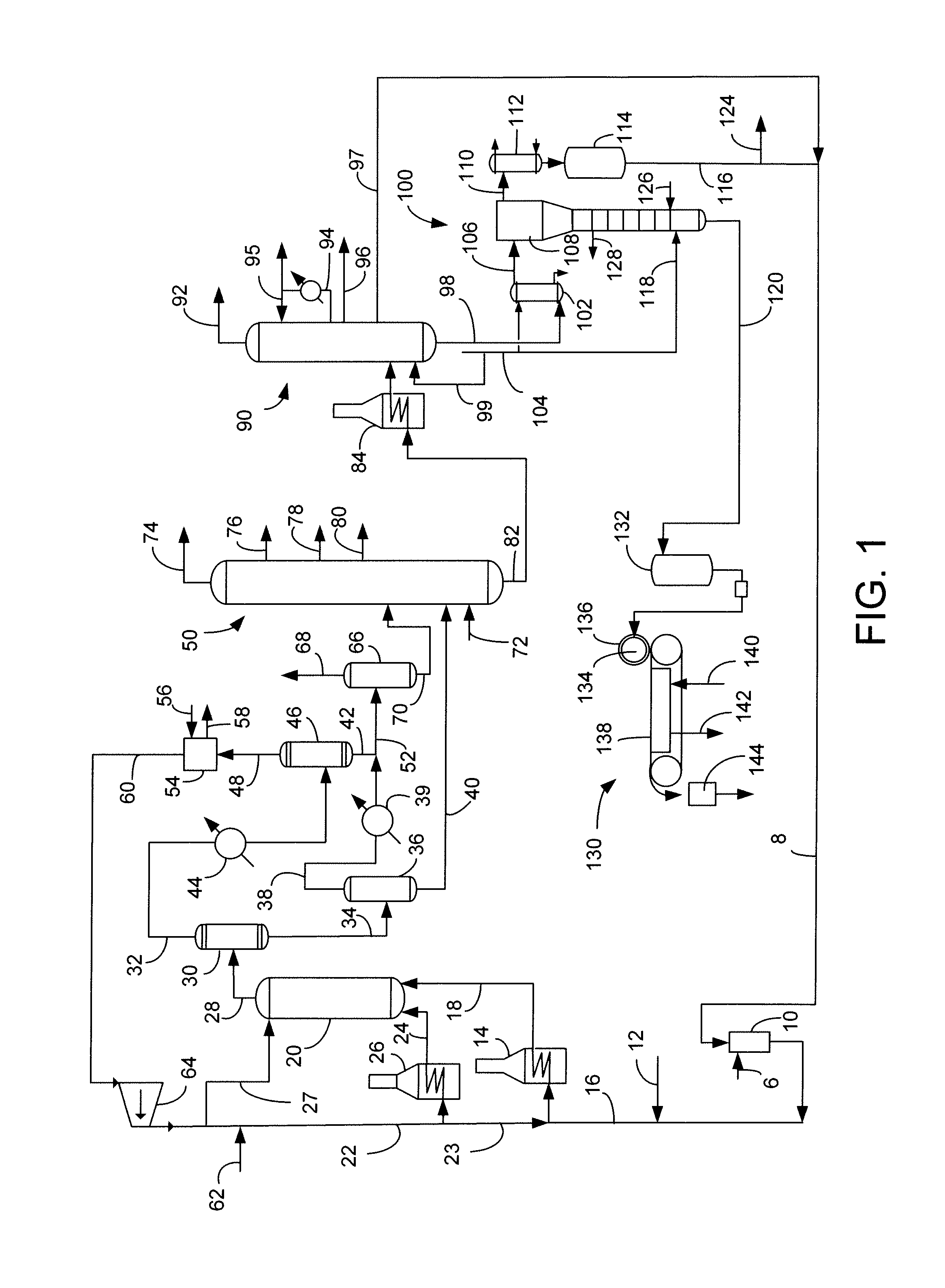
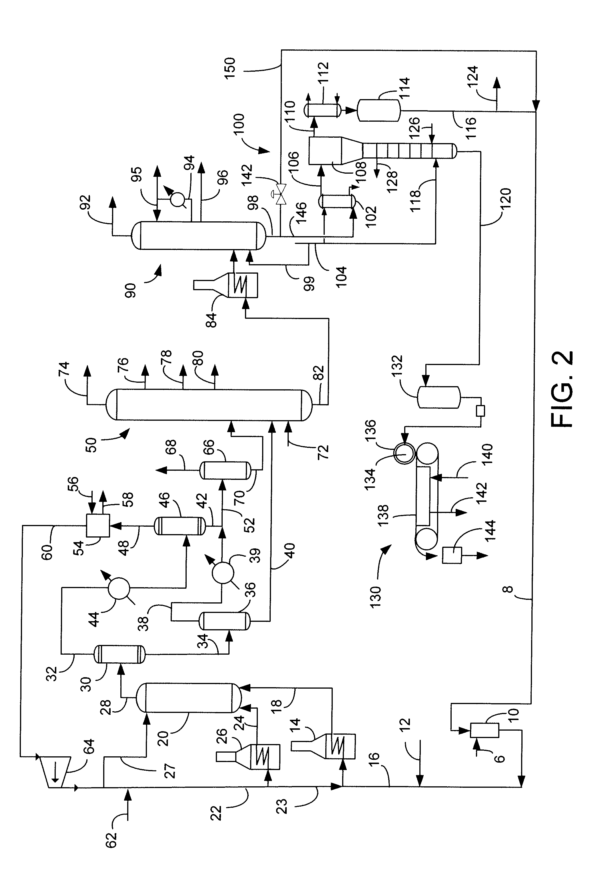
[0009]We have found that utilizing a second vacuum column in the recovery of products from SHC reactor provides pitch that is less sticky and can be solidified more easily. The second vacuum column further separates VGO from pitch and the VGO may be recycled to the slurry hydrocracking reactor. A portion of the pitch from the first vacuum column may be recycled to the slurry hydrocracking reactor. Use of the second vacuum column allows for lower temperatures in both of the vacuum columns which reduces coking and cracking concerns. Pitch byproduct may then be formed into solid particles that are free-flowing bulk solids that can be more easily managed at expected transportation temperatures. Use of two vacuum columns also enables lower pitch temperature to avoid coking in heating apparatuses. Pitch with VGO concentrations under 14 wt-% do not become sticky in their solid form when subjected to anticipated transportation temperatures.

Problems solved by technology

The pitch byproduct is solid at room temperature and has minimum pumping temperatures in excess of 250° C., which make it impractical to move over any great distance, since the pipeline would need to be jacketed with hot oil or electrically heated.
Hence, tank storage requires stirring or circulation to prevent settling, an additional capital and operating expense.
The onset of sticking, or softening point, is difficult to determine and may require time-consuming empirical tests, for example by consolidating the solids under the expected load in a silo, followed by measuring the shear force required to move the solids.
However, this information tells nothing about the onset of softness and cannot be directly used to determine at what point the solid will undergo plastic deformation, or start to stick together.
Solidification of pitch can be accompanied by dust generation because pitch with a higher onset of softening point can become brittle.
However, pitch with lower onset of softening point can become sticky which makes handling in bulk difficult.

Method used


Image

  • Apparatus for Separating Pitch from Slurry Hydrocracked Vacuum Gas Oil
  • Apparatus for Separating Pitch from Slurry Hydrocracked Vacuum Gas Oil
  • Apparatus for Separating Pitch from Slurry Hydrocracked Vacuum Gas Oil

Examples


example

[0040]To determine which pitch materials can be solidified and transported 66° C. (150° F.) was taken as a highest temperature to which pitch materials would be exposed during transportation, considering an acceptable safe operating margin. Pitch materials would have to be transportable up to this maximum temperature without beginning to stick together. That is, the onset of softening temperature of the pitch must be greater than 66° C. (150° F.).

[0041]A procedure for using a thermomechanical analyzer (TMA) is similar to a procedure reported for measuring densities of powdered molding polymer by McNally, G. and McCourt, M., DENSITY MEASUREMENT OF THERMOPLASTIC POWDERS DURING HEATING AND COOLING CYCLES USING THERMAL MECHANICAL ANALYSIS, ANTEC 2002 Conference Proceedings, 1956-1960. A TMA Model Q400 from TA Instruments of New Castle, Del. was used to measure the melting onset temperature and the fusion temperature. About 10 mg of hand-ground, unsized pitch powder was introduced in a 7...


PUM


Abstract

An apparatus is disclosed for converting heavy hydrocarbon feed into lighter hydrocarbon products. The heavy hydrocarbon feed is slurried with a particulate solid material to form a heavy hydrocarbon slurry and hydrocracked in a slurry hydrocracking unit to produce vacuum gas oil (VGO) and pitch. A first vacuum column separates VGO from pitch, and a second vacuum column further separates VGO from pitch. As much as 15 wt-% of VGO can be recovered by the second vacuum column and recycled to the slurry hydrocracking unit. A pitch composition is obtained which can be made into particles and transported without sticking together.

Description

BACKGROUND OF THE INVENTION[0001]This invention relates to a process and apparatus for the treatment of crude oils and, more particularly, to the hydroconversion of heavy hydrocarbons in the presence of additives and catalysts to provide useable products and further prepare feedstock for refining conversion units such as FCC or hydrocracking.[0002]Hydroconversion processes for the conversion of heavy hydrocarbon oils to light and intermediate naphthas of good quality and for reforming feedstocks, fuel oil and gas oil are well known. These heavy hydrocarbon oils can be such materials as petroleum crude oil, atmospheric tower bottoms products, vacuum tower bottoms products, heavy cycle oils, shale oils, coal-derived liquids, crude oil residuum, topped crude oils and the heavy bituminous oils produced from oil sands. Of particular interest are the oils produced from oil sands and which contain wide boiling range materials from naphthas through kerosene, gas oil, pitch, etc., and which ...

Claims


Application Information

Patent Timeline
IPC IPC(8): B01J8/20
CPCC10G47/00
Inventor MCGEHEE, JAMES F.MYERS, DAVID N.VAN WEES, MARKZIMMERMAN, PAUL R.KLEINWORTH, RUTH BUSKUS
Owner UOP LLC
Learn More