Intracorporeal gas exchange devices, systems and methods

Active Publication Date: 2010-12-30
UNIVERSITY OF PITTSBURGH
View PDF19 Cites 57 Cited by
  • Summary
  • Abstract
  • Description
  • Claims
  • Application Information

AI Technical Summary

Benefits of technology

[0040]The devices of the present invention provide significant advantages over previously studied intracorporeal/intravascular gas exchange devices. To be effective and obtain clinical acceptance, such devices are preferably safe in operation, effective, and amenable to easy insertion. In general, these criteria require an intravascular device to be relatively small in size. In general, increased gas exchange efficiencies (both CO2 removal and O2 exchange) of the devices and systems of the present invention, allow the devices and systems to be fabricated with relatively small outer diameters. The devices of the present invention can, for example, be used for respiratory support of patients with acute or acute on

Problems solved by technology

Lung disease remains one of the major healthcare problems present in the United States today.
The breakdown of the capillary-alveolar barrier leads to alveolar flooding and an eventual deterioration of gas exchange capability.
As indicated by the high mortality rates for the lung conditions, however, each therapy has associated limitations which can interrupt patient discharge from the hospital and/or recovery.
Multiple pharmacologic strategies have been investigated since the 1960's, but despite therapeutic benefits, none of the investigated treatments have demonstrated an ability to improve patient survival.
To avert thrombosis within the circuit, patient blood is continuously anticoagulated and bleeding is a major risk whether internal (intercranial) or from cannula dislodgement.
Patients are paralyzed and/or heavily sedated to minimize movement causing dislodgement, which creates a high risk scenario for decubitis ulcers.
Also, the continuous exposure of the blood to artificial sur

Method used


Image

  • Intracorporeal gas exchange devices, systems and methods
  • Intracorporeal gas exchange devices, systems and methods
  • Intracorporeal gas exchange devices, systems and methods

Examples


Embodiment Construction

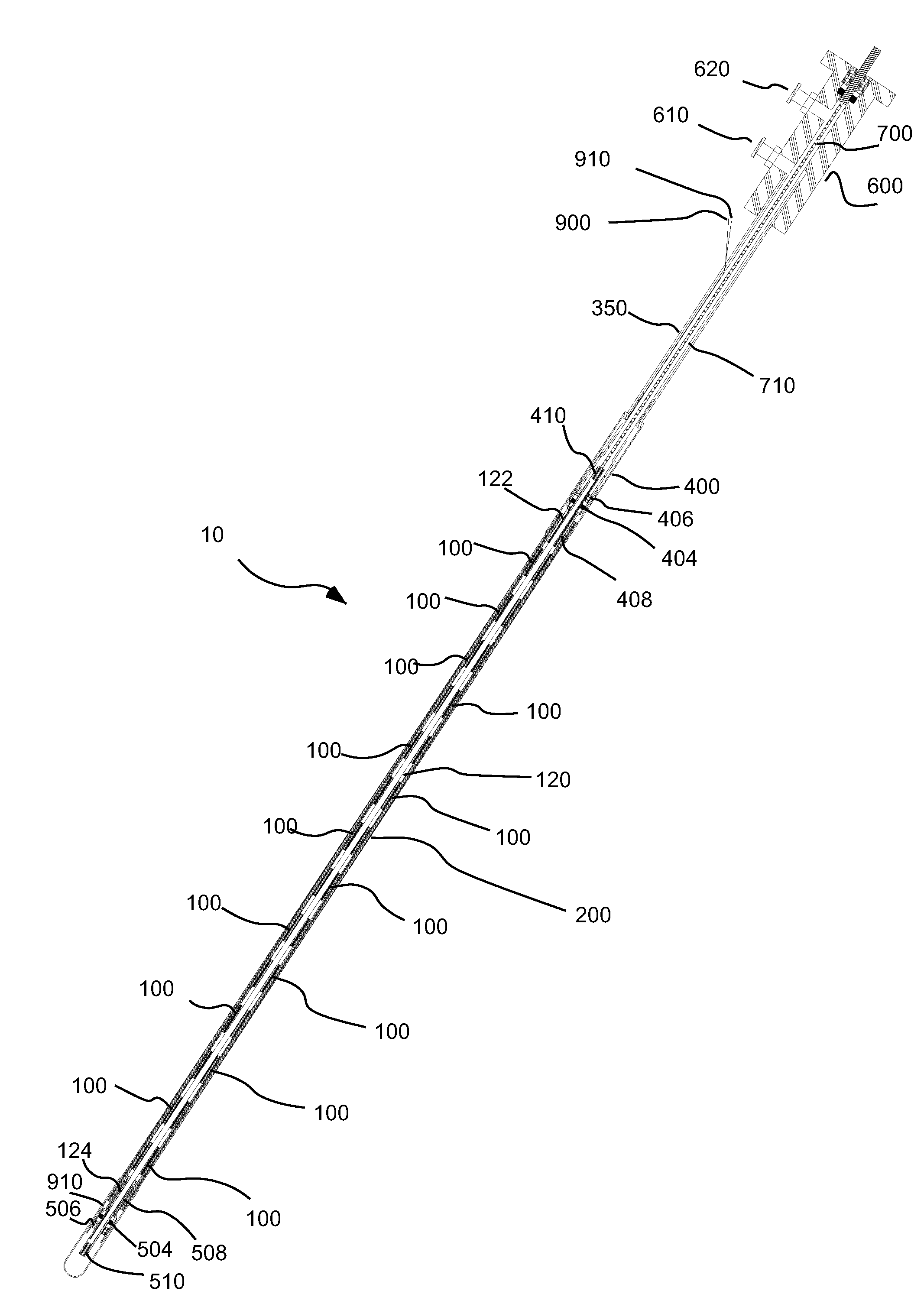
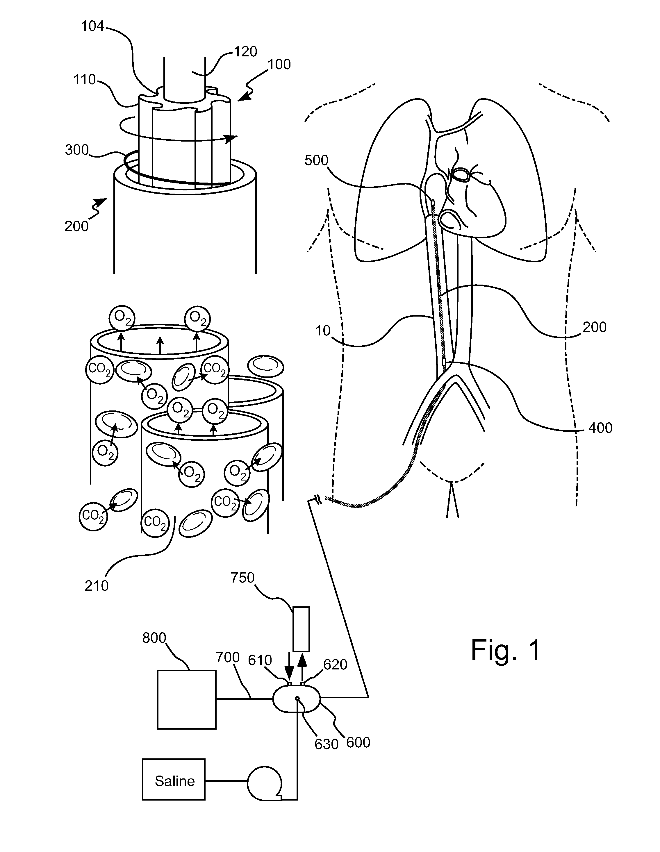
[0102]In several embodiments, the present invention provides intracorporeal respiratory assist devices that can, for example, be inserted in a percutaneous manner similar to insertion of a catheter which are operable to at least partially support native lung function in patients with, for example, acute respiratory distress syndrome and / or acute exacerbations of chronic obstructive pulmonary disease. Intravascular devices of the present invention are sometimes referred to herein as catheters. As described above, primary current clinical therapies (including pharmacotherapy, mechanical ventilation, and ECLS) are associated with patient injury and high mortality rates. The devices of the present invention can be used in combination with or as an alternative to such clinical therapies to reduce patient injury and mortality.

[0103]Although the devices, systems and methods of the present invention are discussed primarily herein in connection with oxygenation of and removal of carbon dioxi...


PUM


Abstract

A system for intracorporeal gas exchange includes a flexible, rotatable shaft; a plurality of axially spaced agitation mechanisms positioned on the rotatable shaft, such that the rotatable shaft can flex between the axially spaced agitation mechanisms; a plurality of hollow gas permeable fibers adapted to permit diffusion of gas between intracorporeal fluid and an interior of the hollow fibers. The plurality of hollow fibers is positioned radially outward from the agitation mechanisms. A blood contacting medical system includes at least one seal, and a purge system via which a flushing fluid is introduced under pressure over a blood-side face of the seal and caused to flow through a space on the blood side of the seal. The system can further include a rotatable member. The space on the blood side of the seal can be in fluid connection with an annular space adjacent to a rotating element operatively connected to the rotatable member.

Description

CROSS-REFERENCE TO RELATED APPLICATION[0001]The present application claims benefit of U.S. Provisional Patent Application Ser. No. 60 / 026,735, filed Feb. 7, 2008, the disclosure of which is incorporated herein by reference.GOVERNMENTAL INTEREST[0002]This invention was made with government support under grant HL070051 awarded by the National Institute of Health: National Heart, Lung and Blood Institute. The government has certain rights in this invention.BACKGROUND OF THE INVENTION[0003]The present invention relates to intracorporeal gas exchange devices, systems and methods and, particularly, to devices, systems and method to effect gas exchange within a patient's vascular structure.[0004]The following information is provided to assist the reader to understand the invention disclosed below and the environment in which it will typically be used. The terms used herein are not intended to be limited to any particular narrow interpretation unless clearly stated otherwise in this documen...

Claims


Application Information

Patent Timeline
IPC IPC(8): A61M37/00
CPCA61M1/1678A61M2025/0031A61M2025/0057B01D63/02A61M5/14A61M1/262A61M2005/1403B01D2313/025B01D2313/105B01D2313/125B01D2313/20A61M2005/006A61M1/26A61M37/00
Inventor FRANKOWSKI, BRIAN J.FEDERSPIEL, WILLIAM J.MIHELC, KEVIN M.LIEBER, SAMUEL C.
Owner UNIVERSITY OF PITTSBURGH
Why Eureka
Try Eureka