Silver alloy, sputtering target material thereof, and thin film thereof

a silver alloy and target material technology, applied in the direction of conductive materials, non-conductive materials with dispersed conductive materials, spectral modifiers, etc., can solve the problems of insufficient improvement of the resistance of the alloy to sulfurization, and achieve excellent heat resistance, high resistance to sulfurization, and high heat resistance

Active Publication Date: 2011-01-06
FURUYA KINZOKU KK
View PDF1 Cites 3 Cited by
  • Summary
  • Abstract
  • Description
  • Claims
  • Application Information

AI Technical Summary

Benefits of technology

[0021]The silver alloy of the present invention exhibits high heat resistance by the synergetic action of Cu and Ge and high resistance to sulfurization by the presence of Ge. The silver alloy consequently has excellent heat resistance and high resistance to sulfurization at the same time. Therefore, when the silver alloy is made into a reflecting electrode film, the obtained reflecting electrode film is very reduced in the lowering of reflectance caused by thermal deterioration and has resistance to yellowing caused by sulfurization even if it is processed through a heating step in a process of producing a flat display such as a color liquid crystal display or in a process of producing a self-emitting type display such as an organic EL and inorganic EL or LED. Also, because the silver alloy is improved in weatherability, the silver alloy thin film according to the present invention may be utilized as reflecting films of optical disk mediums, thin type semi-transmissive films, the structural members of electronic parts such as LEDs and as reflecting films of light parts such as a headlamp and projector lamp. Also, the silver alloy thin film may be utilized as an electromagnetic shielding film. The silver alloy thin film according to the present invention may be utilized a silver alloy paste.

Problems solved by technology

Also, sulfurization is promoted by heating and the resistance of the alloy to the sulfurization has been improved only insufficiently.

Method used


Image

  • Silver alloy, sputtering target material thereof, and thin film thereof
  • Silver alloy, sputtering target material thereof, and thin film thereof
  • Silver alloy, sputtering target material thereof, and thin film thereof

Examples


example 1

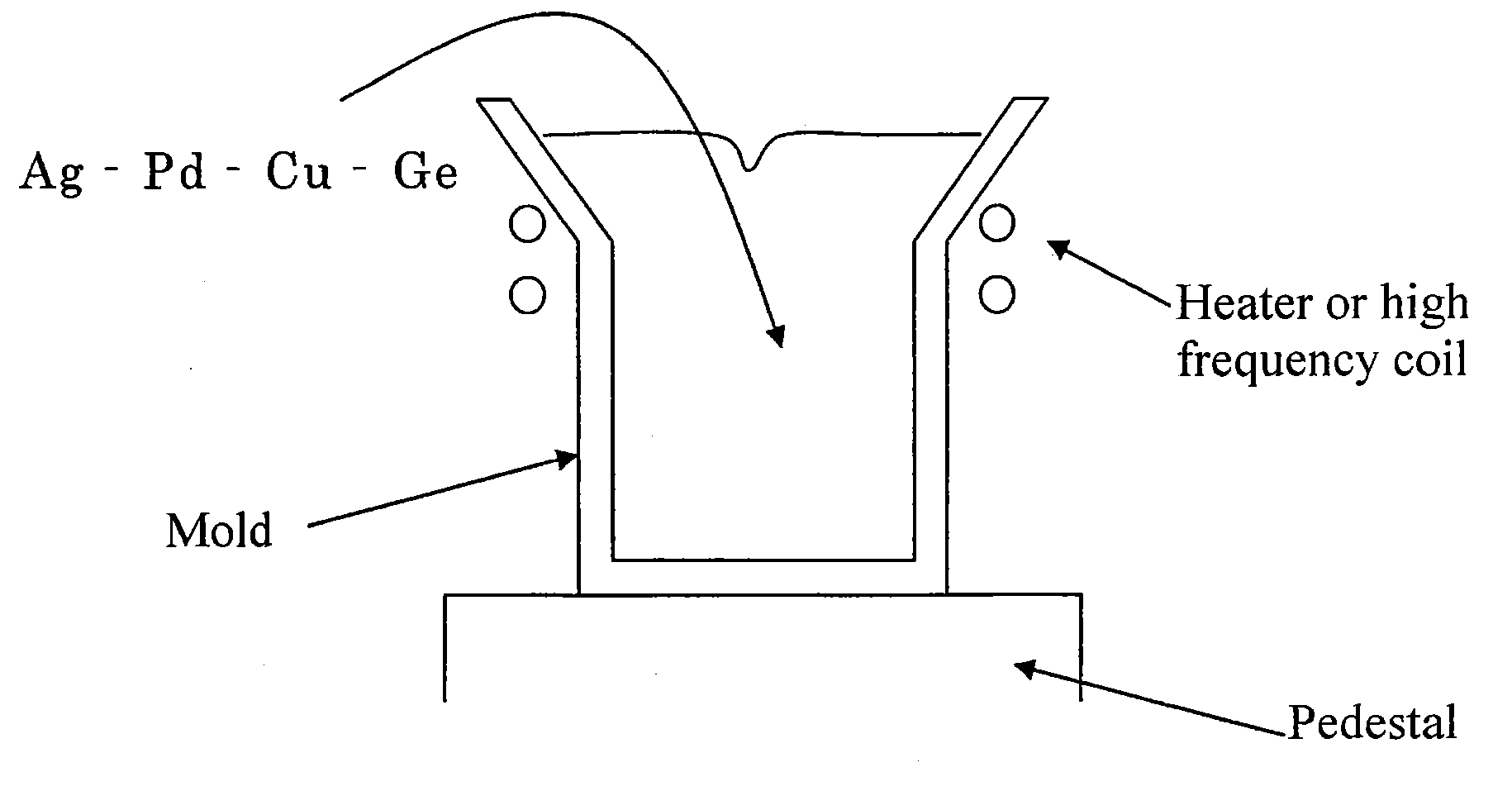
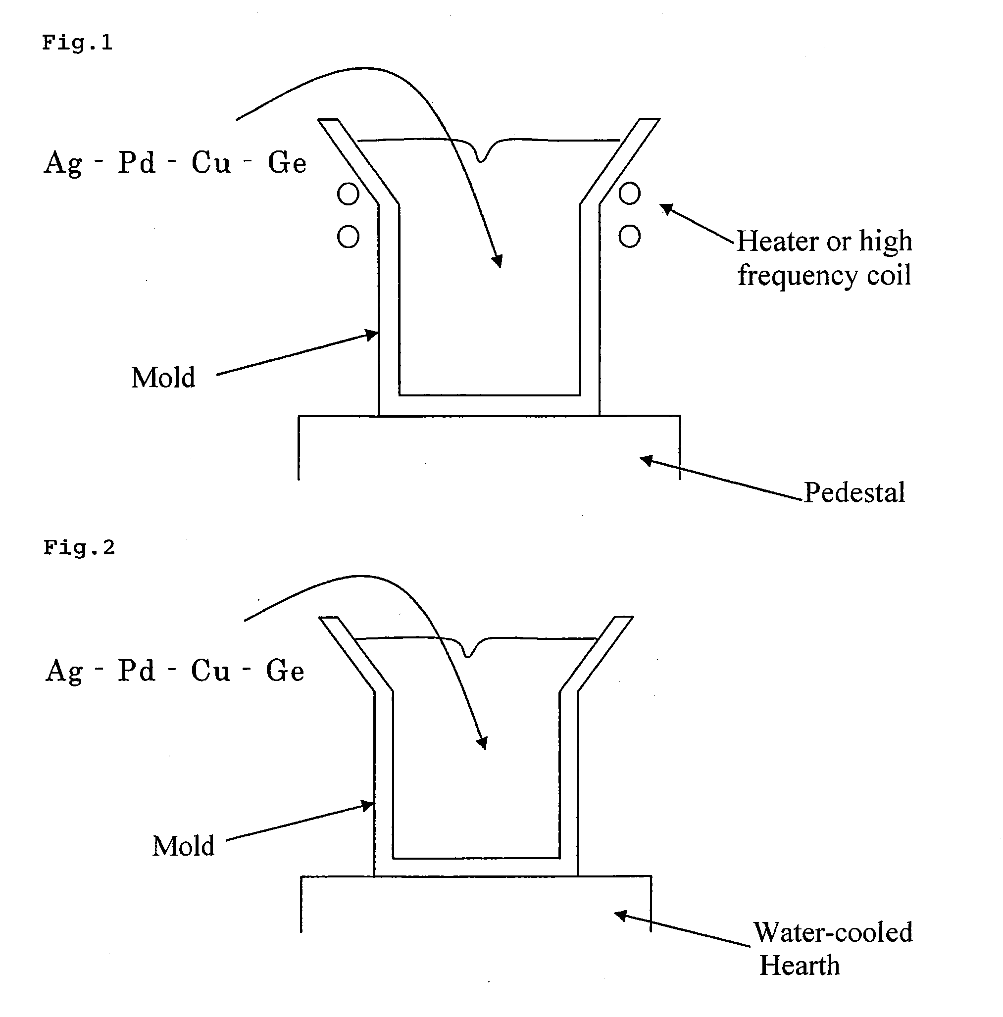
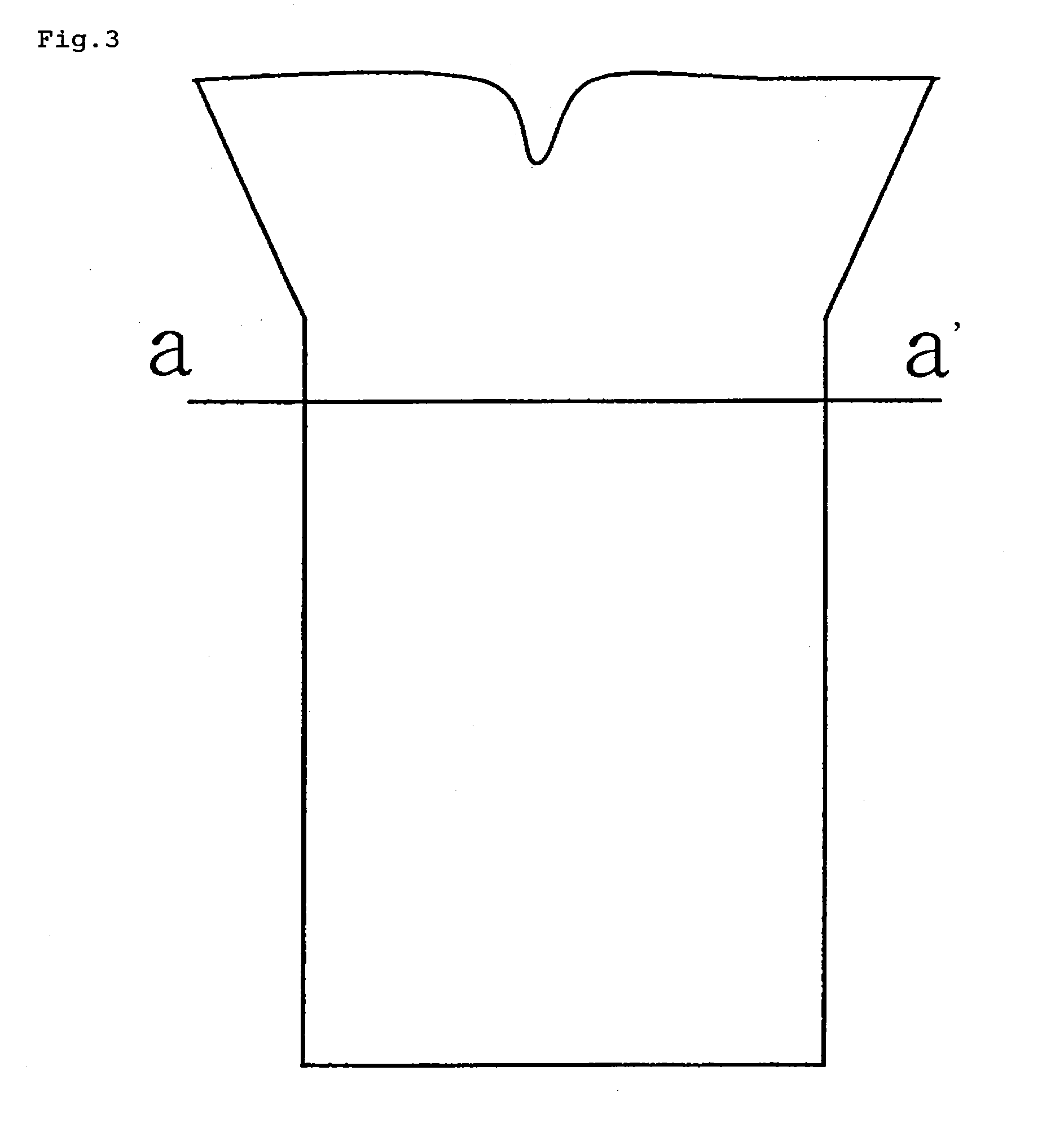
[0053]A silver alloy sputtering target material composed of 98.7 Ag-0.8 Pd-0.3 Cu-0.2 Ge (this means that Ag content: 98.7 wt %, Pd content: 0.8 wt %, Cu content: 0.3 wt %, Ge content: 0.2 wt %, hereinafter, the composition of the silver alloy will be shown by this notation) was produced according to the method described in the embodiment. Using this silver alloy sputtering target material, a silver alloy reflecting film having the above composition was formed on a quartz glass substrate having a smooth surface by a sputtering method as Example 1. The thickness of the film was 200 nm. An AFM (Atomic Force Microscope, manufactured by Seiko Instruments Inc., Model No. SPA300HV) image of the formed thin film is shown in FIG. 4(a). At this time, the results of surface roughness analysis are as follows: Ra (nm): 1.410, RMS (nm): 1.785 and P-V (nm): 14.07. Also, the reflectance of the silver alloy thin film of Example 1 was measured by a spectrophotometer (manufactured by Shimadzu Corpora...

example 2

[0054]The silver alloy thin film of Example 1 was subjected to heat treatment carried out at 250° C. for one hour in the air. The resulting sample was obtained as Example 2. The silver alloy thin film of Example 2 was also observed by an AFM in the same manner as in Example 1. The obtained AFM image is shown in FIG. 6(a). At this time, the results of surface roughness analysis were as follows: Ra (nm): 1.693, RMS (nm): 2.203 and P-V (nm): 24.55. Also, the reflectance of the silver alloy thin film of Example 2 was measured in the same manner as in Example 1. The results are shown in FIG. 7.

example 3

[0065]A silver alloy sputtering target material composed of 98.4 Ag-0.8 Pd-0.3 Cu-0.5 Ge was produced according to the method described in the embodiment. Using this silver alloy sputtering target material, a silver alloy reflecting film having the above composition was formed on a quartz glass substrate having a smooth surface by a sputtering method. The thickness of the film was 200 nm. The silver alloy thin film was subjected to heat treatment carried out at 250° C. for one hour in the air. The resulting sample was obtained as Example 3. The silver alloy thin film of Example 3 was also observed by an AFM in the same manner as in Example 1. The obtained AFM image is shown in FIG. 8(a). At this time, the results of surface roughness analysis were as follows: Ra (nm): 1.727, RMS (nm): 2.314 and P-V (nm): 28.06. Also, the reflectance of the silver alloy thin film of Example 3 was measured in the same manner as in Example 1. The results are shown in FIG. 9.


PUM

PropertyMeasurementUnit
reflectanceaaaaaaaaaa
RHaaaaaaaaaa

Abstract

It is an object of the present invention to provide a Ag—Pd—Cu—Ge type silver alloy which can form a reflective electrode film having such two characteristics that it is very reduced in the lowering of reflectance caused by thermal deterioration and has resistant to yellowing caused by sulfurization even after a heating step in a process of producing a color liquid crystal display. The silver alloy according to the present invention includes a composition containing at least four elements including Ag as its major component, 0.10 to 2.89 wt % of Pd, 0.10 to 2.89 wt % of Cu and 0.01 to 1.50 wt % of Ge, and the total amount of Pd, Cu and Ge is 0.21 to 3.00 wt %.

Description

TECHNICAL FIELD[0001]The present invention relates to a silver alloy superior in heat resistance and resistance to sulfurization, to a sputtering target material having the composition of the silver alloy and to a thin film or a paste of the silver alloy. Also, the silver alloy thin film is adaptable to various uses, for example, displays such as liquid crystal displays or a reflecting film, reflecting electrode film, electrode film or wiring of electronic parts such as LEDs (emitting diode). The silver alloy thin film is also adaptable to uses for a reflecting film and thin semi-transmissive film of optical disk mediums or reflecting films of light parts such as headlights and projection lamps of projectors and may also be used as an electromagnetic wave shielding film.BACKGROUND ART[0002]It is demanded of the reflecting electrode film of a color liquid crystal display to have heat resistance enough to stand against heating because it is heated to about 250° C. in the heating step ...

Claims


Application Information

Patent Timeline
Patent Type & Authority Applications(United States)
IPC IPC(8): C22C5/08H01B1/02G02F1/361B32B15/20B32B3/10B32B3/26C23C14/34C22C5/06C23C14/18C23C14/58
CPCC23C14/3414C03C17/3647C23C14/5806C23C14/58C03C17/09C03C17/3671C03C17/40C03C17/3676C23C14/5866C03C17/36Y10T428/24917Y10T428/21Y10T428/12993C23C14/185C22C5/06C03C17/3663C23C14/34
Inventor WATANABE, ATSUSHI
Owner FURUYA KINZOKU KK
Why Eureka
Try Eureka