
Production of steam and its application to enhanced oil recovery

a technology of enhanced oil recovery and steam, which is applied in the direction of lighting and heating apparatus, fluid removal, water/sludge/sewage treatment, etc., can solve the problems of mineral contaminants in the water, carbonates, sulfates and silica, and the tendency to leave mineral contaminants in the steam generator or boiler, etc., to achieve less chemical substances, less waste of resources, and the effect of quick and easy operation

Inactive Publication Date: 2011-01-13
TOTAL PUTEAUX FR
View PDF9 Cites 18 Cited by
  • Summary
  • Abstract
  • Description
  • Claims
  • Application Information

AI Technical Summary

Benefits of technology

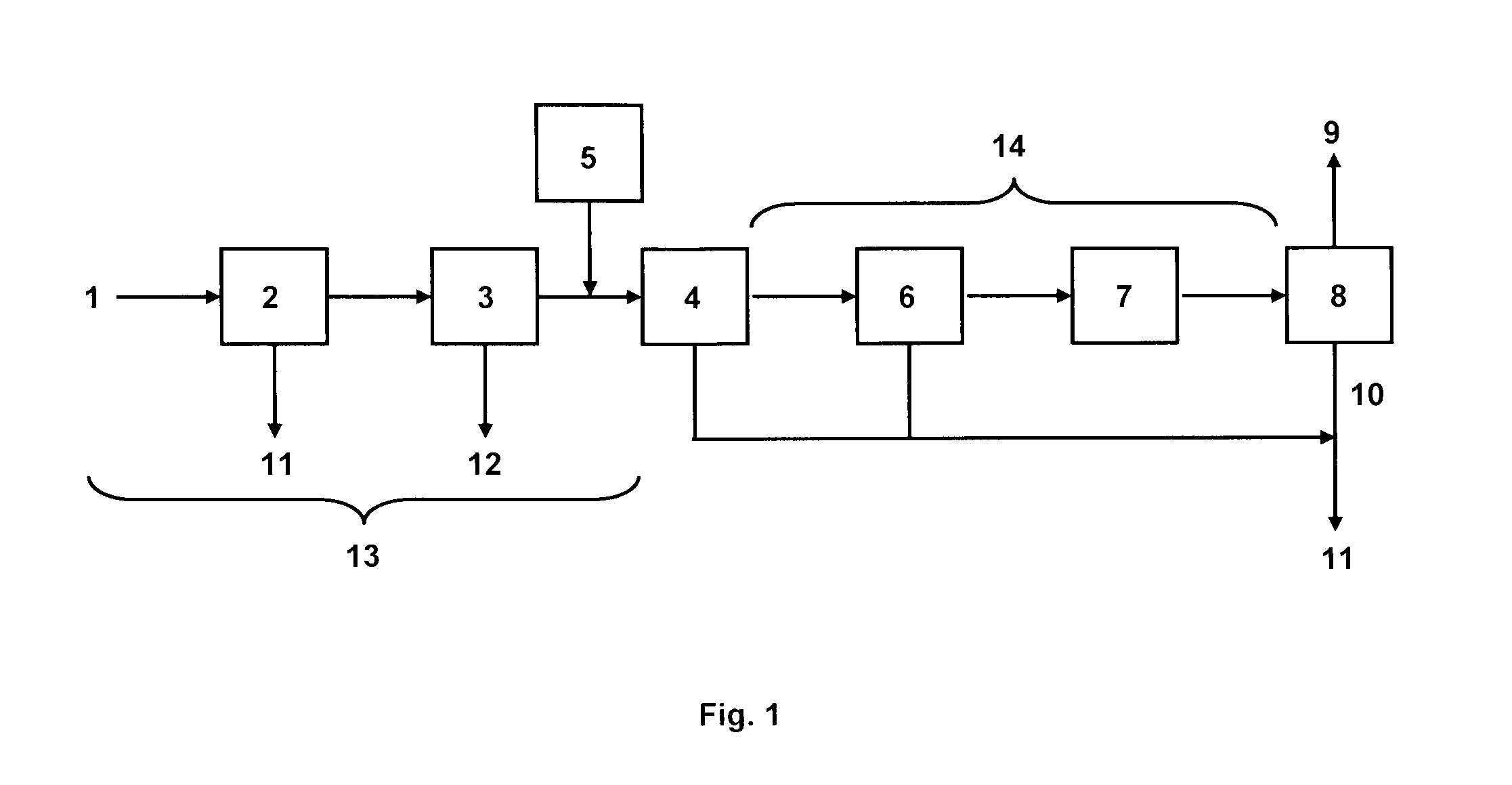
[0066]The present invention enables to overcome the drawbacks of the prior art. In particular the invention provides an improved process for removing carbonate and / or sulfate ions from boiler feedwater, namely a quicker process, wherein it is possible to use small sized-equipment and / or less chemical substances.
[0067]This is achieved by using a crystallizing reagent which is able to react with carbonate and / or sulfate ions in order to produce carbonate and / or sulfate micro crystals and a ceramic membrane for filtering the water and eliminating the carbonate and / or sulfate crystals.
[0068]As the ceramic membrane can retain and eliminate crystals having a small size, it is not necessary to perform an extensive crystallization, since a moderate crystallization will be sufficient for effectively removing the carbonates and / or sulfates. Accordingly, it is possible to add the crystallizing reagent in a moderate amount and / or to avoid using large equipment and / or to remove carbonate and / or sulfate ions in a quick and efficient manner.

Problems solved by technology

One of the problems involved in the generation of steam is indeed the presence of mineral contaminants in the water, mainly carbonates, sulfates and silica.
As water is heated and converted into steam, the mineral contaminants tend to be left in the steam generator or boiler.
Scale acts as an insulator, reducing boiler efficiency.
Scaling can lead to boiler tube failure due to overheating.
For carbonate and bicarbonate species, such phenomena may be detrimental to the application since they may decompose at high temperature producing acidic steam in equilibrium with alkaline water.
The complexity of the water treatment scheme required depends on the development scheme (whether or not there is a recycling of the produced water to feed the boiler), the feed-water specifications, and the type of boiler.
Conversely, there are other instances where silica is not the primary concern (for example because the produced water is not recycled to boiler feedwater and / or because the primary source of feedwater is poor in silica) but where carbonate and / or sulfate ions are a major issue (for example because the primary source of feedwater is rich in carbonate and / or sulfate ions).
However, large quantities of chemical substances are generally required; besides, the decantation time is high and the corresponding settling tanks are very large.
However this option is not feasible in view of the large water tank volumes which would be required for its implementation.
However, in both cases the process is ineffective for removing large quantities of carbonate or sulfate ions.

Method used


Image

  • Production of steam and its application to enhanced oil recovery

Examples


example 1

[0125]Produced water is treated according to the claimed invention. The mineral composition of the water is the following:

Sodium: 2200 mg / LPotassium:  62 mg / LCalcium:   3 mg / LMagnesium:   6 mg / LCarbonates:  108 mg / LBicarbonate: 2677 mg / LSulfate:  56 mg / LChloride: 1697 mg / LLithium:0Strontium:   1 mg / LBarium:  0.2 mg / LIron:  1.2 mg / LBorous:0Silica:0Formiates:0Acetate:0pH:8.8Salinity from CI−5 g / LSpecific gravity at 20° C.1.001

[0126]Calcium chloride is added to the water as the crystallizing reagent, at a concentration of 5.2×10⁻³ mol / L. The crystallization process generates a suspension of crystals in the produced water. Duration does not have to be so long as to promote the growth of large crystals of calcium carbonate and calcium sulfate.

[0127]The produced water with the precipitated crystals is directed to the ceramic membrane. The ceramic membrane produces a reject stream having the insoluble carbonate and sulfate salts therein. Permeate produced by the ceramic membrane may be dir...

example 2

[0129]Produced water is treated according to the claimed invention. The mineral composition of the water is the following:

Sodium: 2200 mg / LPotassium:  62 mg / LCalcium:   3 mg / LMagnesium:   6 mg / LCarbonates:   0 mg / LBicarbonate: 2785 mg / LSulfate:  800 mg / LChloride: 1697 mg / LLithium:0Strontium:   0 mg / LBarium: 0.2mg / LIron: 1.2mg / LBorous:0Silica:0Formiates:0Acetate:0pH:7.9Salinity from Cl−—Specific gravity at 20° C.1

[0130]Calcium chloride is added to the water as the crystallizing reagent, at a concentration of 1.3×10⁻² mol / L. The crystallization process generates a suspension of crystals in the produced water. Duration does not have to be so long as to promote the growth of large crystals of calcium carbonate and calcium sulfate.

[0131]The produced water with the precipitated crystals is directed to the ceramic membrane. The ceramic membrane produces a reject stream having the insoluble carbonate and sulfate salts therein. Permeate produced by the ceramic membrane may be directed downst...


PUM

PropertyMeasurementUnit
Densityaaaaaaaaaa
Densityaaaaaaaaaa
Densityaaaaaaaaaa

Abstract

The invention relates to a method for producing steam comprising the successive steps of:providing feedwater containing carbonate and / or sulfate ions;adding a crystallizing reagent able to react with carbonate and / or sulfate ions to the feedwater, in order to produce carbonate and / or sulfate crystals;filtering the feedwater with a ceramic membrane to produce a permeate stream;supplying the permeate stream to a boiler; andgenerating steam in the boiler.The invention also relates to an installation adapted for implementing said method, as well as to a process for extracting hydrocarbons from a subterranean formation using the abovementioned method for producing steam.

Description

TECHNICAL FIELD[0001]The present invention relates to a method for producing steam and to an installation adapted for implementing said method. The invention also relates to a method for extracting hydrocarbons from a subterranean formation using the steam thus produced.TECHNICAL BACKGROUND[0002]Producing the world's enormous reserves of immobile heavy oil or mobile oil with high viscosity located beyond the reach of open pit mining techniques requires the use of thermal processes. These processes deliver heat to the reservoir in one way or another to heat the oil and mobilize it for production. The dominant thermal processes are:[0003]Steam Assisted Gravity Drainage;[0004]Steam Drive; and[0005]Cyclic Steam Stimulation.[0006]Steam Assisted Gravity Drainage (SAGD) is a thermal recovery technique widely used for the recovery of extra heavy oils, in which pairs of horizontal injector and producer wells are drilled within the drains roughly 5 m apart. Steam is injected to heat and mobil...

Claims


Application Information

Patent Timeline
IPC IPC(8): E21B43/22C02F1/58C02F1/68C02F1/42C02F1/44
CPCF22D11/006E21B43/24
Inventor AUDIBERT-HAYET, ANNIE
Owner TOTAL PUTEAUX FR
Learn More