The process is not suitable for producing RFID antenna laminates, since the
layout of patterns based on foil tearing produces a far too inaccurate result.
Publication WO01 / 54226 discloses a process, which is nearly consistent with the above-cited one and the accuracy of which is not enough for manufacturing for example a
chip attachment area or a coil antenna.
However, the method lends itself poorly to the
mass production of an RFID antenna laminate because, due to the product's properties, a predominant portion of the
metal foil must be removed and its removal by
laser evaporation is tedious, expensive, and also technically challenging as the substrate material must not be damaged.
In addition, an
adhesive coating shall remain on the substrate material in areas from which the metal foil has been removed, which is why the product is not suitable for the manufacture of
high security level articles, such as passports and credit cards.
The method might lend itself well to cases which do not require the production of thin lines and interline spaces, but the method is poorly applicable to the
mass production of a typical RFID antenna laminate: The method requires that the
cutting of a metal foil be done along a line beyond the edge of an
adhesive pattern in order to ensure that the rest of the foil would be certainly off and removable after a
cutting operation.
The application of an
adhesive involves always a certain degree of positional and dimensional inaccuracy and, in addition, the adhesive pattern has often a tendency to spread out upon bonding the materials together, which further increases the positional
instability regarding the edge of an adhesive pattern.
When this is topped up by the positional and dimensional inaccuracy of a
cutting process, it is obvious that the method does not enable the manufacture of typical RFID antennas with narrow interline spaces.
Moreover, as a result of what has been described above, the edges of a remaining foil pattern are in practice unavoidably out of contact with the substrate material, which is generally unacceptable within a
chip attachment area of the antenna.
For the above reasons, it is poorly suitable for manufacturing an RFID antenna laminate, perhaps with the exception of cases in which the antenna comes in a very simple design.
A definite majority of RFID antennas are such that antenna laminates containing the same cannot be manufactured with this method.
Besides, the use of a laminate in place of a mere metal foil increases manufacturing costs.
There is no essential difference from the preceding ones, and thereby it has the same limitations and poor adaptability to the
mass production of RFID antenna laminates.
The method may lend itself well to cases, which do not require the production of
thin line pitches and interline spaces and in which a
chip can be attached to an antenna, and the antenna, along with its chip, can be laminated for a part of the inflexible structure in the same manufacturing process as the one used for making the antenna, but the method is poorly suitable for the mass production of a typical RFID antenna laminate: Because of the tool,
stamping can only be used for manufacturing such antennas in which the line
pitch is quite large.
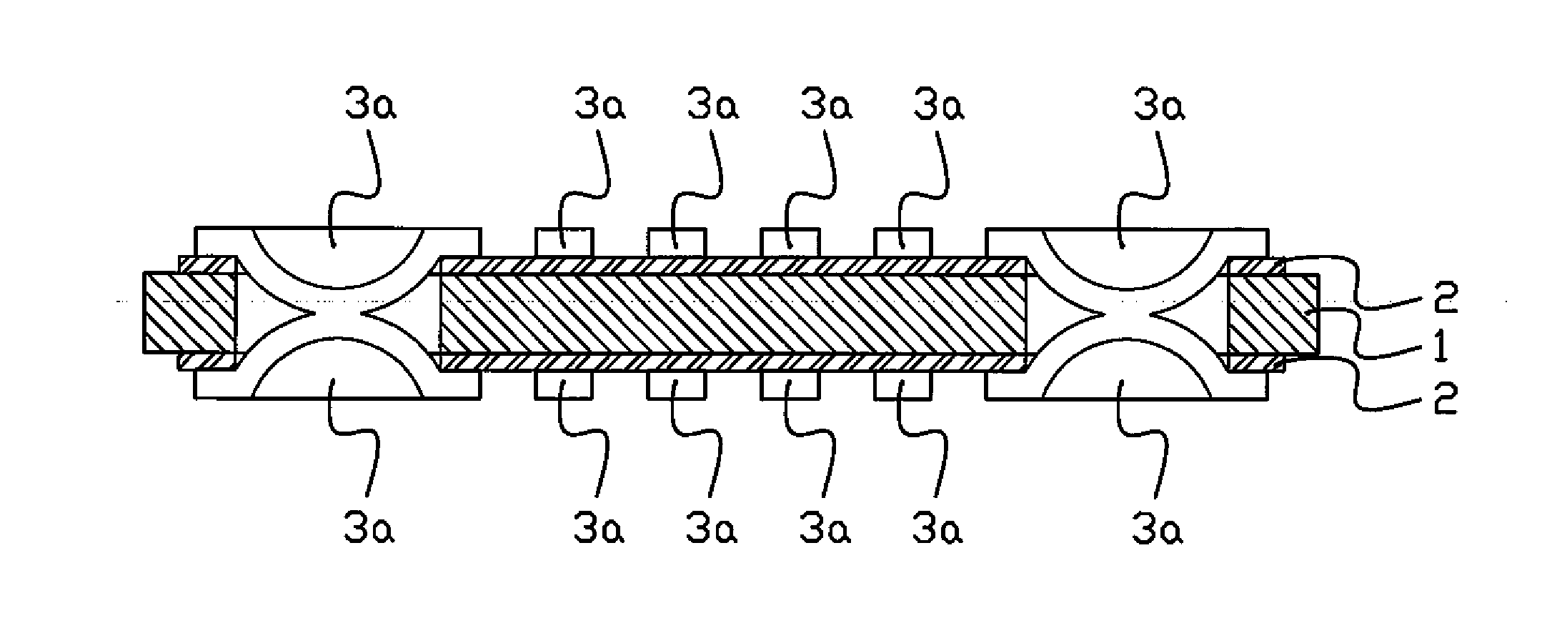
Making even a simple RFID chip attachment area is impossible because, first of all, the open-bent and
dielectric-filled
cut results in the attachment area becoming convex and, secondly, it is practically impossible to apply a
dielectric in such a way that it would not spread over those foil surfaces to which the chip is to be electrically bonded.
More complex chip attachment areas, including several electrically isolated surfaces, cannot be manufactured at all.
In addition, one of the main features of the process according to the cited publication is that, because of a
stamping operation, the foil surface must be provided with a synthetic film which would have to be removed at least from RFID antennas in preparation for further
processing, and all this increases complexity and costs of the process.
This method involves limitations similar to the preceding method and, thus, it is not generally applicable to the mass production of an RFID antenna laminate.
The above-cited methods cannot be used in mass production for the manufacture of chip-carrying RFID tags.

