
Polymer coated inorganic fine particle and method for preparing the same

a technology of inorganic fine particles and polymer coatings, which is applied in the field of polymer coating inorganic fine particles and a method for preparing the same, can solve the problems of insufficient feature of the method disclosed in the non-patent literature, inability to evenly coat each of the fine particles, and thick polymer coatings, etc., to achieve the effect of short time duration and removal of unnecessary ingredients

Inactive Publication Date: 2011-01-13
TAMAGAWA SEIKI CO LTD
View PDF6 Cites 8 Cited by
  • Summary
  • Abstract
  • Description
  • Claims
  • Application Information

AI Technical Summary

Benefits of technology

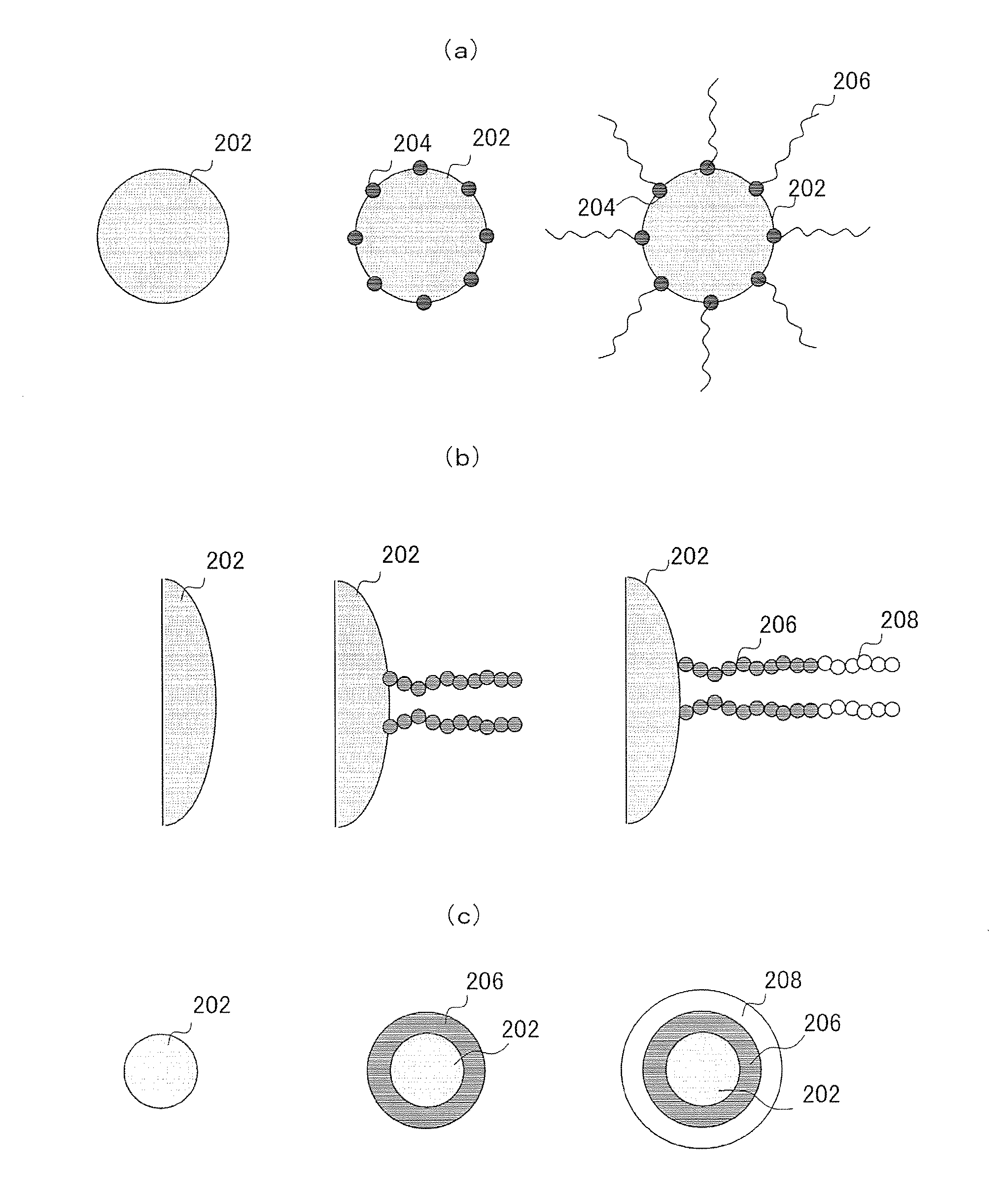
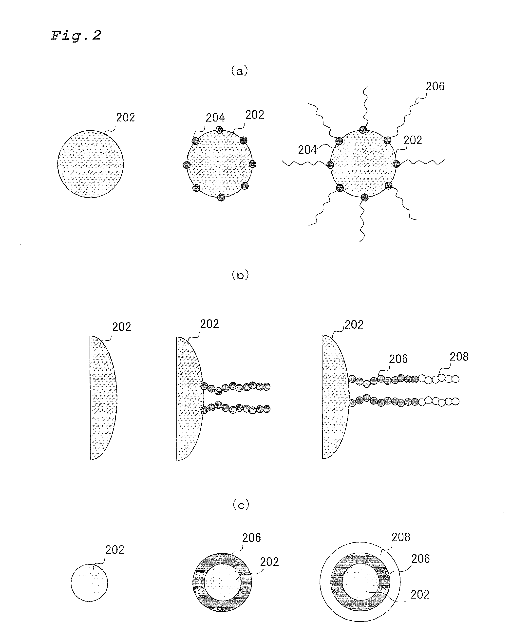
[0049]According to the present invention, the polymer coated inorganic fine particles with the features of being formed the graft chains of the polymer on the inorganic fine particle surface, being able to control the polymerization precisely while being coated thinly one by one with the polymer.
[0050]Hereinafter, the present invention will be described in detail by referring to drawings while describing practical embodiments.
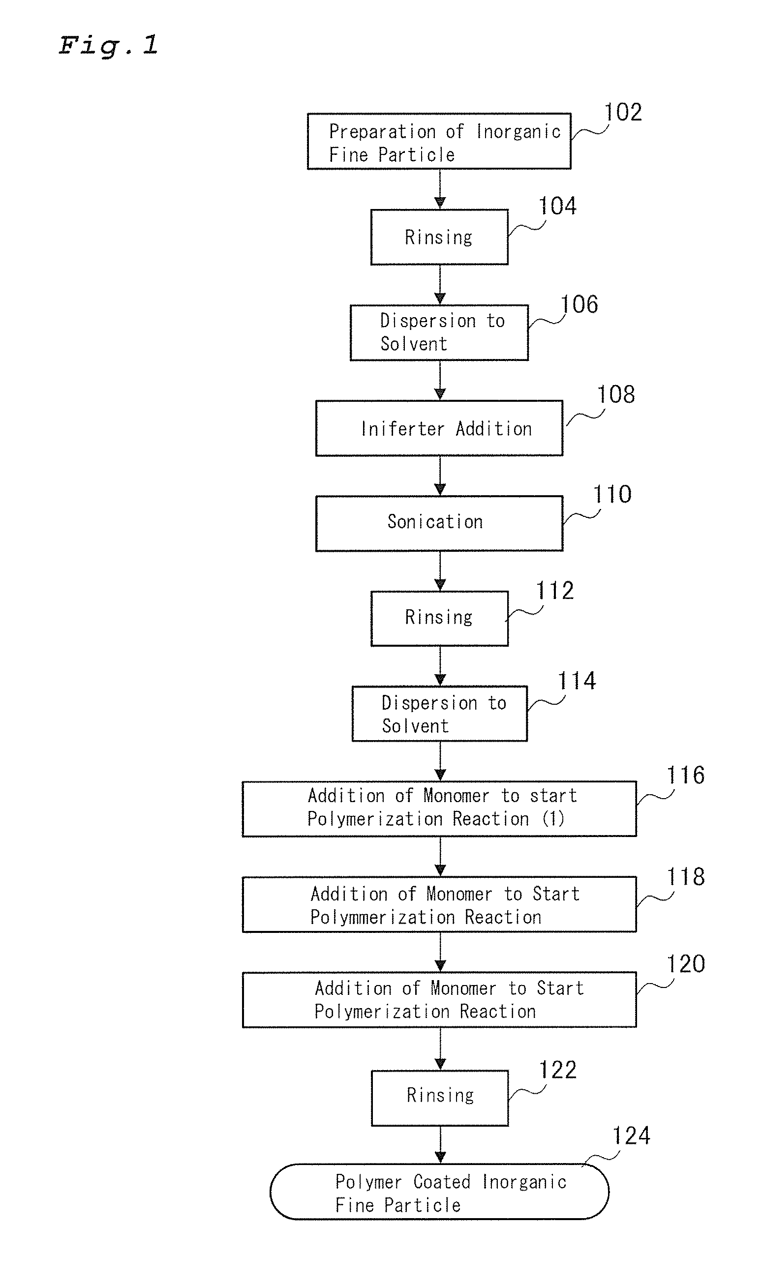
[0052]FIG. 1 shows major process steps for preparing the polymer coated inorganic fine particles in one practical embodiment of the present invention. In FIG. 1, the inorganic fine particle is synthesized in the step 102. It is preferred that the inorganic fine particle of the present invention may be particles having the precisely controlled particle diameter and having well matched particle diameter. Such inorganic fine particles may be prepared by for example the thermolysis in a high boiling point solvent the oleic acid iron complex obtained by iron chloride and sodium oleate. By this method, the inorganic fine particle such as ferrite fine particle being precisely controlled in the particle diameter thereof while having well matched particle diameter.
[0053]The inorganic fine particles as such prepared are rinsed in the step 104 to remove unnecessary ingredients. For example, with respect to the ferrite fine particle prepared by the thermolysis of the oleic acid iron complex in the high boiling point solvent, the repeating process of magnetically recovering after precipitating the ferrite fine particle by adding 2-methoxy ethanol may rinse the ferrite fine particles.
[0054]Next in the step 106, the inorganic fine particles are dispersed in a solvent to prepare the dispersion solution followed by addition

Problems solved by technology

However, the methods disclosed in the non-patent literatures have the insufficient feature, for the purpose of precise control of the polymer coating, which is the polymer coating is thick when compared to the particle diameter and can not be able to coat each of fine particles evenly.
However, the polymer coated magnetic fine particles prepared by the above described methods may be able to make narrow in the polymer molecular weight distribution thereof, it could not be considered that the coating of the fine particles by the polymer was well controlled nevertheless such that it could not achieve the polymer coated magnetic fine particle in the monodispersed state in which the magnetic fine polymers were coated one-by-one.
However, in the patent literature 2, the polymerization initiator is present in a monomer solution rather than fixed on the magnetic fine particle surface such that the method disclosed was not the method suitable for applying the polymer coating on the inorganic fine particle one by one.
However, the surface coating method applied to the superparamagnetic fine particle having the average particle diameter of 10 nm is merely applied to the magnetite particles having the average particle diameter of 25 nm as is such that the method does not enable the one by one polymer coating of the ferromagnetic fine particles under the dispersed state.
Furthermore, as described above, the patent literatures 1 and 2 could not be able to coat the particles one by one by the polymer.
As such any methods described in each literature are not a suitable methods for coating thinly one by one the ferromagnetic fine particles.

Method used


Image

  • Polymer coated inorganic fine particle and method for preparing the same
  • Polymer coated inorganic fine particle and method for preparing the same
  • Polymer coated inorganic fine particle and method for preparing the same

Examples


example 1

1) Preparation of Ferrite Particle

[0071]The ferrite particle used for the inorganic fine particle corresponding to the core of the polymer coated magnetic fine particle as prepared according to the method described in Nature Mater. 2004, 3, 891-895 and iron chloride and sodium oleate were reacted to obtain oleic acid-iron complex and then the complex was subjected to thermolysis in a high boiling point solvent.

[0072]The ferrite fine particle obtained was observed by using a transmission electron microscope (TEM, H-7500, Hitachi High-Technologies Corporation., Ltd.). As the result, the ferrite particles of a particle diameter of 19 nm in an almost spherical shape were obtained and a standard deviation of the particle size distribution was 3.2 nm such that the particle size was confirmed to have excellently matched.

2) Synthesis of Iniferter

[0073]An iniferter was synthesized according to FIG. 3. As shown in FIG. 3, 4-chloro-methyl-benzoyl acid chloride was in toluene treated with hydro...

example 2

[0078]Using the ferrite fine particles and the iniferter prepared in Example 1, to the ferrite fine particle was the iniferter fixed using the same procedure in the Example 1 and while keeping 70 Celsius degrees at 200 rpm styrene 0.06 g was added followed by 12 hours polymerization reaction and then styrene 0.02 g, glycidylmethacrylate 0.01 g, and ethyleneglycoldimethacrylate 0.01 g were added to further continue the polymerization reaction for 12 hours. Then, glycidylmethacrylate 0.02 g was added and the polymerization reaction was continued for further 12 hours. After the reaction was completed, the reaction solution was dispersed in toluene and the toluene was centrifugally removed. The sets of toluene dispersion and centrifugal separation were repeated 3 times to remove non-reacted monomers. The obtained polymer coated ferrite fine particles were observed and evaluated by the transmission electron microscope (TEM). An average particle diameter was to be 23.8 nm obtained from TE...

example 3

[0079]Using the ferrite fine particles and the iniferter prepared in Example 1, to the ferrite fine particle was the iniferter fixed using the same procedure in the Example 1 and while keeping 70 Celsius degrees at 200 rpm styrene 0.02 g, glycidylmethacrylate 0.01 g, and ethyleneglycoldimethacrylate 0.01 g were added to further continue the polymerization reaction for another 12 hours. Then, glycidylmethacrylate 0.02 g was added and the polymerization reaction was continued for further 12 hours. After the reaction was completed, the reaction solution was dispersed in toluene and the toluene was centrifugally removed. The sets of toluene dispersion and centrifugal separation were repeated 3 times to remove non-reacted monomers. The obtained polymer coated ferrite fine particles were observed and evaluated by the transmission electron microscope (TEM). An average particle diameter was to be 20.6 nm obtained from TEM images of 100 particles and a standard deviation thereof was to be 3....


PUM

PropertyMeasurementUnit
Thicknessaaaaaaaaaa
Particle sizeaaaaaaaaaa
Particle size distributionaaaaaaaaaa

Abstract

An object of the present invention is to provide a polymer coated magnetic fine polymer by coating an inorganic fine particle with a thin polymer layer under precise control of a polymerization reaction and a method for preparing the same. Onto a surface of the inorganic fine particle the iniferter is fixed and grafted chains are formed on the inorganic fine particle by a living radical polymerization using the iniferter as an initiator which is defined by the following chemical formula:(wherein X is a hydrophilic atomic group being capable of binding to a surface of the inorganic fine particle, R1 and R2 are each independently selected from a mono-valent hydrocarbyl group which is formed by removing one hydrogen atom from hydrocarbon.)

Description

TECHNICAL FIELD[0001]The present invention relates to a polymer coated inorganic fine particle and a method for preparing the same, and more particularly relates to a polymer coated inorganic fine particle and a preparation method thereof, which is able to provide mono-dispersion by coating one inorganic fine particle with a thin polymer layer.BACKGROUND OF INVENTION[0002]Complex particles which comprise inorganic particles in nano-meter size with polymer coating on the surfaces thereof are applied in various field and have been utilized so far. Recently in bio-technology and medical fields, studies on various applications of inorganic fine particles such as nano-meter sized magnetic fine particles coated with polymer on the surface thereof become particularly popular.[0003]Such studies on the inorganic fine particle coated with polymer may include applications for bio-sensors and affinity carriers, and the studies have been extensively made particularly for about magnetic fine part...

Claims


Application Information

Patent Timeline
IPC IPC(8): H01F1/36C07F7/18H01F1/00B05D5/00
CPCB82Y30/00C01P2004/64C01P2004/04C01P2004/84C08F2/38C08F2/44C08F292/00C08F293/005C08F2438/03C08J5/005C09C1/42C09C3/12C01P2004/03C01P2004/62C08F220/10C08F212/08
Inventor HANDA, HIROSHIABE, MASANORIHATAKEYAMA, MAMORUSAKAMOTO, SATOSHINISHIO, KOSUKEMASAIKE, YUKAKISHI, HIROSHI
Owner TAMAGAWA SEIKI CO LTD
Learn More