High-power pulse magnetron sputtering apparatus and surface treatment apparatus using the same

a magnetron sputtering and high-power pulse technology, applied in the direction of electrolysis components, vacuum evaporation coatings, coatings, etc., can solve the problems of surface roughness of workpieces, rate reduction, coating quality decline, etc., to achieve high uniformity, high quality coating, good adhesion

Inactive Publication Date: 2011-01-20
INST NUCLEAR ENERGY RES ROCAEC
View PDF6 Cites 46 Cited by
  • Summary
  • Abstract
  • Description
  • Claims
  • Application Information

AI Technical Summary

Benefits of technology

In view of the disadvantages of prior art, the object of the present invention is to provide a magnetron

Problems solved by technology

Consequently, the surface roughness of the workpiece is increased and thus the coating quality is decreased.
Although there are already many prior-art methods for filtering out those microparticles existed in the plasma of the arc plasma coating process by increasing the amount of curved magnetic channels, despite of such methods will cause the deposition rate to decrease, it still can not prevent the workpiece from being contaminated by certain micron-scaled microparticles as they can travel passing such curved magnetic channels and reach the workpiece surface, causing adverse affect in relation to the coating quality.
However, since the sputtering material is primarily composed of neutral atoms and atom clouds, the said magnetron sputtering coating is disadvantageous in its low the ionization ratio that it is generally lower than 5% and thus the adhesion of a film resulting from the magnetron sputtering coating is poor.
Moreover, since the working area of the said magnetron sputtering coating is usually very narrow so that the workpiece can only be placed in front of the target of about 5˜10 cm distance, the said magnetron sputtering coating is insufficient for coating large-sized workpieces.
Although there are prior-art methods capable of enhancing the ionization of the neutral atoms in the sputtering material by the use of an additional ion source, such methods can only provide little improvement but it is operating at a

Method used


Image

  • High-power pulse magnetron sputtering apparatus and surface treatment apparatus using the same
  • High-power pulse magnetron sputtering apparatus and surface treatment apparatus using the same
  • High-power pulse magnetron sputtering apparatus and surface treatment apparatus using the same

Examples


Embodiment Construction

For your esteemed members of reviewing committee to further understand and recognize the fulfilled functions and structural characteristics of the invention, several exemplary embodiments cooperating with detailed description are presented as the follows.

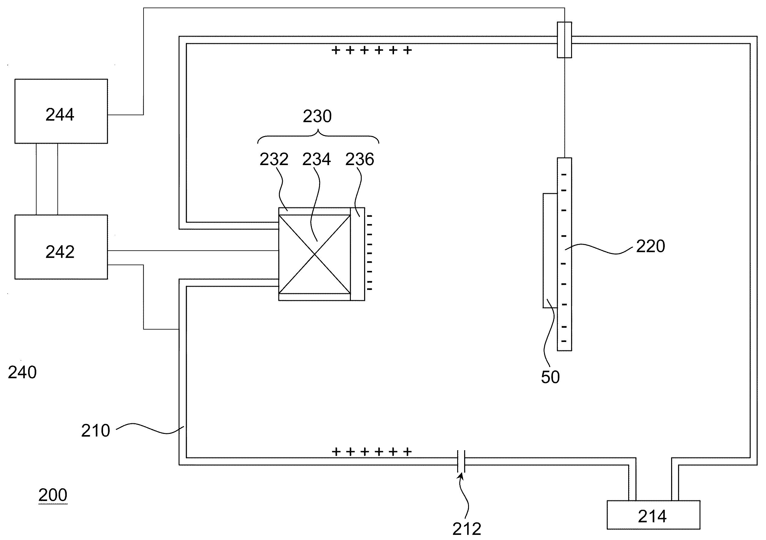
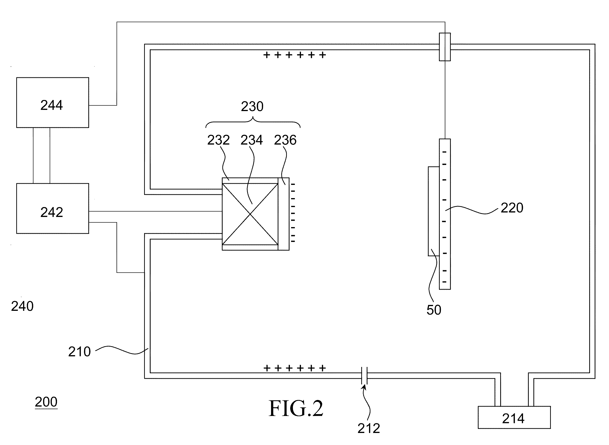
Please refer to FIG. 2, which is a schematic diagram showing a magnetron sputtering apparatus according to an exemplary embodiment of the invention. In FIG. 2, the magnetron sputtering, apparatus 200 adapted for coating a film on a workpiece 50, includes a vacuum chamber 210, a holder 220, a magnetron plasma source 230 and a high-power pulse power supply set 240, in which the holder 220 and the magnetron plasma source 230 are correspondingly disposed inside the vacuum chamber 210 at two opposite positions, and the high-power pulse power supply set 240 is coupled to the vacuum chamber 210, the magnetron plasma source 230 and the holder 220.

In addition, the magnetron plasma source further comprises a base 232, a magnetron controller 2...


PUM

PropertyMeasurementUnit
Fractionaaaaaaaaaa
Timeaaaaaaaaaa
Timeaaaaaaaaaa

Abstract

A magnetron sputtering apparatus suitable for coating on a workpiece is provided. The magnetron sputtering apparatus includes a vacuum chamber, a holder, a magnetron plasma source and a high-power pulse power supply set, wherein the magnetron plasma source includes a base, a magnetron controller and a target. A reactive gas is inputted into the vacuum chamber, and the holder supporting the workpiece is disposed inside the vacuum chamber. The magnetron plasma source is disposed opposite to the workpiece, wherein the magnetron controller is disposed in the base, and the target is disposed on the base. The high-power pulse power supply set is coupled to the vacuum chamber, the magnetron plasma source and the holder, and a high voltage pulse power is inputted to the magnetron plasma source to generate plasma to coat a film on the surface of the workpiece.

Description

FIELD OF THE INVENTIONThe present invention relates to a magnetron sputtering apparatus and surface treatment apparatus using the same, and more particularly, to a high-power pulse magnetron sputtering apparatus and its relating surface treatment apparatus.BACKGROUND OF THE INVENTIONGenerally, there are two types of plasma coating techniques usually used in industry, which are arc plasma coating and magnetron sputtering coating. For the technique of arc plasma coating, it is usually performed in a vacuum environment of about 10−3 torr for producing plasma between a cathode electrode and an anode electrode by means of a low-voltage discharge of about tens of volt, by that a target placed on the cathode electrode can be ionized into plasma and thus deposited upon a workpiece. It is noted that when a large current is used for producing arc, it can result the plasma to have a high degree of ionization. Hence, the arc plasma coating is advantageous in its good coating adhesion to the wor...

Claims


Application Information

Patent Timeline
IPC IPC(8): C23C14/35
CPCH01J37/3405H01J37/3467H01J37/3444
Inventor WU, JIN-YULIUNG, WEN-LUNGTSAI, MING-JUIJAN, DER-JUNHSIEH, CHENG-CHANGWEI, SHIN-WULEE, CHIA-CHENGAI, CHI-FONG
Owner INST NUCLEAR ENERGY RES ROCAEC
Why Eureka
Try Eureka