Method of producing microfluidic device

a microfluidic device and microfluidic technology, applied in the direction of laboratory glassware, instruments, suspensions, etc., can solve the problems of reducing the productivity (yield) prone to deformation retaining strength, and reducing the efficiency of the microfluidic device, so as to suppress the occurrence of non-joint parts, improve the adhesion thereof, and reduce the yield

Inactive Publication Date: 2011-01-20
CANON KK
View PDF8 Cites 2 Cited by
  • Summary
  • Abstract
  • Description
  • Claims
  • Application Information

AI Technical Summary

Benefits of technology

[0006]There exists a method in which at least any one of the substrate layer 100 and the cover layer 300 is formed of comparatively flexible material to improve adhesion thereof, suppressing the occurrence of the non-joint portion. The material used in the method is comparatively flexible, however, the method uses the deformation of the material, so that the retaining strength of deformation is prone to deform a microfluidic device 1000 itself. Since the deformation causes an error in dimension in the fine structure to cause an individual difference in the microfluidic device 1000 produced by the method, which may lower controllability. That leads to decrease in the productivity (yield) of the microfluidic device 1000.
[0007]The present invention has been made in view of such problems and has its object to solve the problems. Furthermore, the object of the present inventio

Problems solved by technology

The material used in the method is comparatively flexible, however, the method uses the deformation of the material, so that the retaining strength of deformation is prone to deform a microfluidic device 1000 itself.
Since the deformation causes an

Method used


Image

  • Method of producing microfluidic device
  • Method of producing microfluidic device
  • Method of producing microfluidic device

Examples


embodiments

First Embodiment

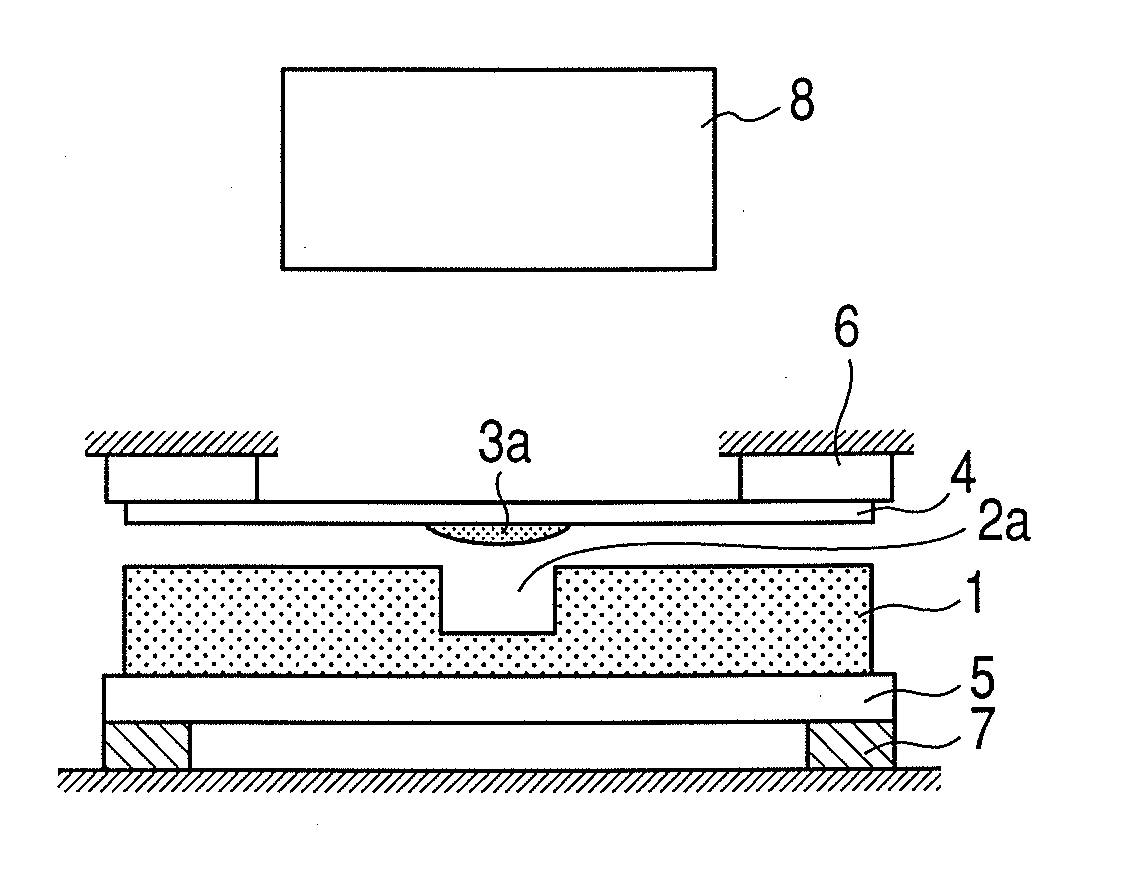
[0035]A first embodiment of the present invention is described with reference to FIG. 1 to FIGS. 4A and 4B.

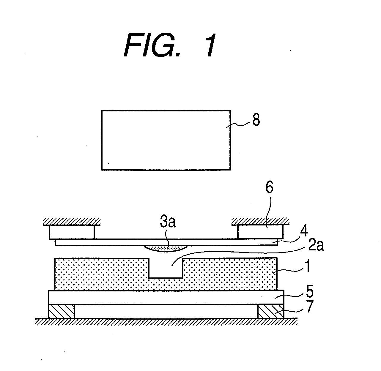
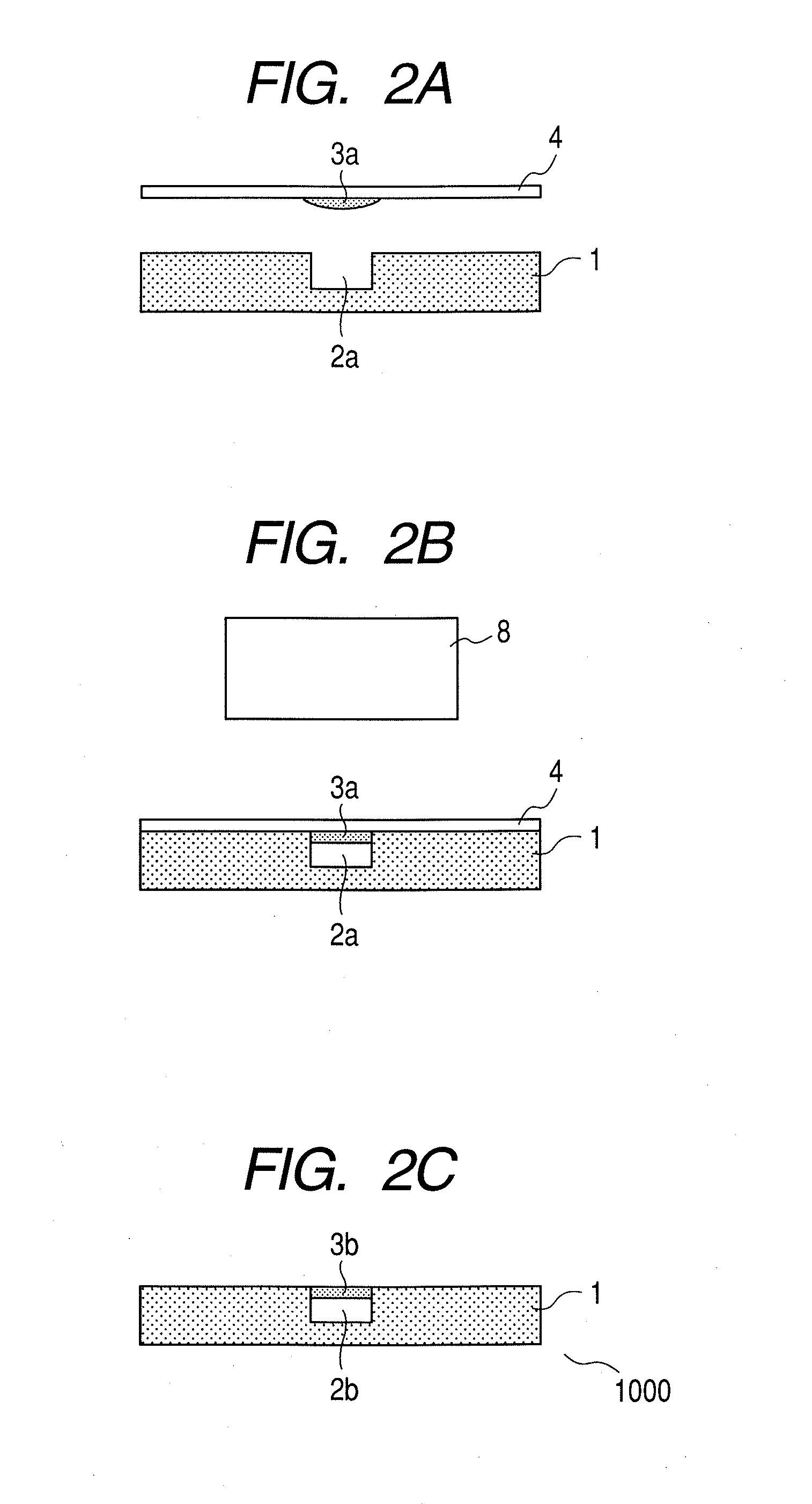
[0036]FIG. 1 is a schematic diagram of the configuration of an apparatus describing the first embodiment of the present invention. In FIG. 1, a substrate 1 is formed of plastic or glass and provided with a fine depressed portion 2a such as a groove being a channel and a hole being a chamber. The apparatus also includes an ultraviolet (UV) curable resin 3 (the ultraviolet curable resin still to be cured is represented by 3a, and hereinafter the cured UV curable resin is represented by 3b).

[0037]The UV curable resin 3a is adhered on the face of the quartz substrate 4 opposing the substrate 1. The face of the quartz substrate 4 opposing the substrate 1 is preferably subjected in advance to a surface treatment. More specifically, a release agent such as a silane coupling agent is preferably applied thereto. Since quartz is high in transmittance of ultraviolet rays, ...

second embodiment

[0046]In the first embodiment, a method is described in which the UV curable resin 3a is adhered only to a portion of the quartz substrate 4 opposing the fine depressed portion 2a of the substrate 1, thereby to cause the UV curable resin 3b cured by UV rays to serve as the cover for the fine depressed portion 2a on the substrate 1. In the second embodiment, a method is described in which the UV curable resin 3a is adhered to substantially the entire face of the quartz substrate 4 opposing the substrate 1 and the UV curable resin is caused to serve as the cover for the fine depressed portion 2a on the substrate 1.

[0047]FIGS. 5A and 5B are schematic diagrams describing the second embodiment of the present invention. A shielding film 41 shields ultraviolet rays in FIG. 5A. The film is formed by evaporating metal such as chromium with the portion of the fine depressed portion 2a masked so that the portion can be irradiated with UV rays in view from the UV irradiation unit 8 when the fin...

third embodiment

[0051]In the first and the second embodiment, a method is described in which the UV curable resin 3a is adhered to the quartz substrate 4 in advance and oppose the substrate 1 and then cured by UV rays, thereby to cause the UV curable resin 3b to serve as the cover for the fine depressed portion 2a on the substrate 1. In the third embodiment, a method is described in which the quartz substrate 4 is caused to oppose the substrate 1 and the UV curable resin 3a is sent and cured by UV rays, thereby to cause the UV curable resin 3b to serve as the cover for the fine depressed portion 2a on the substrate 1.

[0052]FIG. 6 is a schematic cross section describing the third embodiment of the present invention. In FIG. 6, water 10 is caused to flow to the fine depressed portion 2a on the substrate 1 while forming a layer and an interface between the water 10 and the UV curable resin 3a. For this reason, there are provided a pipe 11 for sending the UV curable resin 3a and the water 10 and connec...


PUM

PropertyMeasurementUnit
Adhesion strengthaaaaaaaaaa

Abstract

There is provided a method of producing a microfluidic device including a substrate having a depressed portion and a cover member, whereby to reduce the dispersion of a geometric individual difference and the possibility that a non-joint area can occur in a joint portion between the substrate and the cover member. At the time of producing the microfluidic device, the depressed portion serving as a channel, a chamber and a reservoir is formed in advance in the substrate and a liquid-state energy ray curable resin is applied to the surface of the substrate in which the depressed portion is formed. The energy ray curable resin is cured by an energy ray irradiation unit and caused to serve as the cover on the depressed portion of the substrate, thereby to form the channel, chamber and reservoir.

Description

TECHNICAL FIELD[0001]The present invention relates to a microfluidic device and an apparatus using the same.BACKGROUND ART[0002]Micro electro mechanical systems (MEMS) are applied to bionics, environmental analysis and chemical synthesis that draw attention as one of application fields of the MEMS. As such a device, there are known a microfluidic device or micro total analysis systems (μTAS). These devices are such that a channel, a chamber and a reservoir are formed on a substrate of semiconductor, glass, ceramic or plastic, and a sample, reagent or liquid being material for chemical synthesis as a specimen is caused to flow thereinto to perform analysis or chemical synthesis.[0003]These devices have a microscale advantage of reducing the consumption of a solvent, sample and reagent as compared with a conventional analyzing method or batch process and being faster in reaction rate, so that if a practical device can be mass-produced, a simple inspection method can be provided for a ...

Claims


Application Information

Patent Timeline
IPC IPC(8): G01N33/48C08F2/48
CPCB01J19/0093B01J2219/00783B01J2219/00826B01J2219/00831B01J2219/00833B81C1/00071B01L2200/0689B01L2300/0816B01L2300/0887B81B2201/058B01L3/502707
Inventor TOKITA, TOSHINOBU
Owner CANON KK
Why Eureka
Try Eureka