Method and Control System for Controlling a Brushless Electric Motor

Active Publication Date: 2011-02-03
HUNTER DOUGLAS INC +1
View PDF6 Cites 36 Cited by
  • Summary
  • Abstract
  • Description
  • Claims
  • Application Information

AI Technical Summary

Benefits of technology

[0014]A large motor inductance promotes the voltage feedback via the d-current modulation. Likewise, it contributes to smoothing the motor currents and thus to keeping the torque constant. The reason for this is that the dynamic field attenuation allows operating the motor up to a minimum phase voltage and thus intermediate circuit voltage without collapse of the torque. The feedback of energy via the d-current modulation indeed increases the intermediate circuit voltage (boost converter effect), but not always up to the minimum voltage that can be achieved by field attenuation. The remaining voltage difference thus results in that the phase current briefly collapses (pulses) causing torque fluctuations. A large motor inductance, which has to be present anyway due to the large voltage drop caused by dynamic field attenuation, smoothes the pulsating current profile, just as any inductance smoothes out a current profile (energy storage), and ensures that the power flux can be kept nearly constant. From the approach of the differential equation, which leads to an exact solution of the d-current profile as a function of the intermediate circuit voltage, it follows that due to the dynamic field attenuation, the phase voltage and thus, as described, the intermediate circuit voltage can be reduced more than would be possible (at the same id-current peak value) by constant field attenuation, since the differential voltage drops are included in the phase voltage due to the rate of change of the d-current.
[0015]The torque-forming q-current is held constant independently of the d-current o

Problems solved by technology

But in practical usage, the latter have several disadvantages, and specifically in particular a large installation volume and a short service life.
With this technology of the “slender intermediate circuit” particular problems chiefly occur in the main single-phase power supply from the single-phase mains (standard main AC supply frequency e.g. 50 or 60 Hz), because the rectified DC voltage pulsates very strongly at twice the main frequency (e.g. 100 Hz or 120 Hz) between zero and a peak va

Method used


Image

  • Method and Control System for Controlling a Brushless Electric Motor
  • Method and Control System for Controlling a Brushless Electric Motor
  • Method and Control System for Controlling a Brushless Electric Motor

Examples


Example

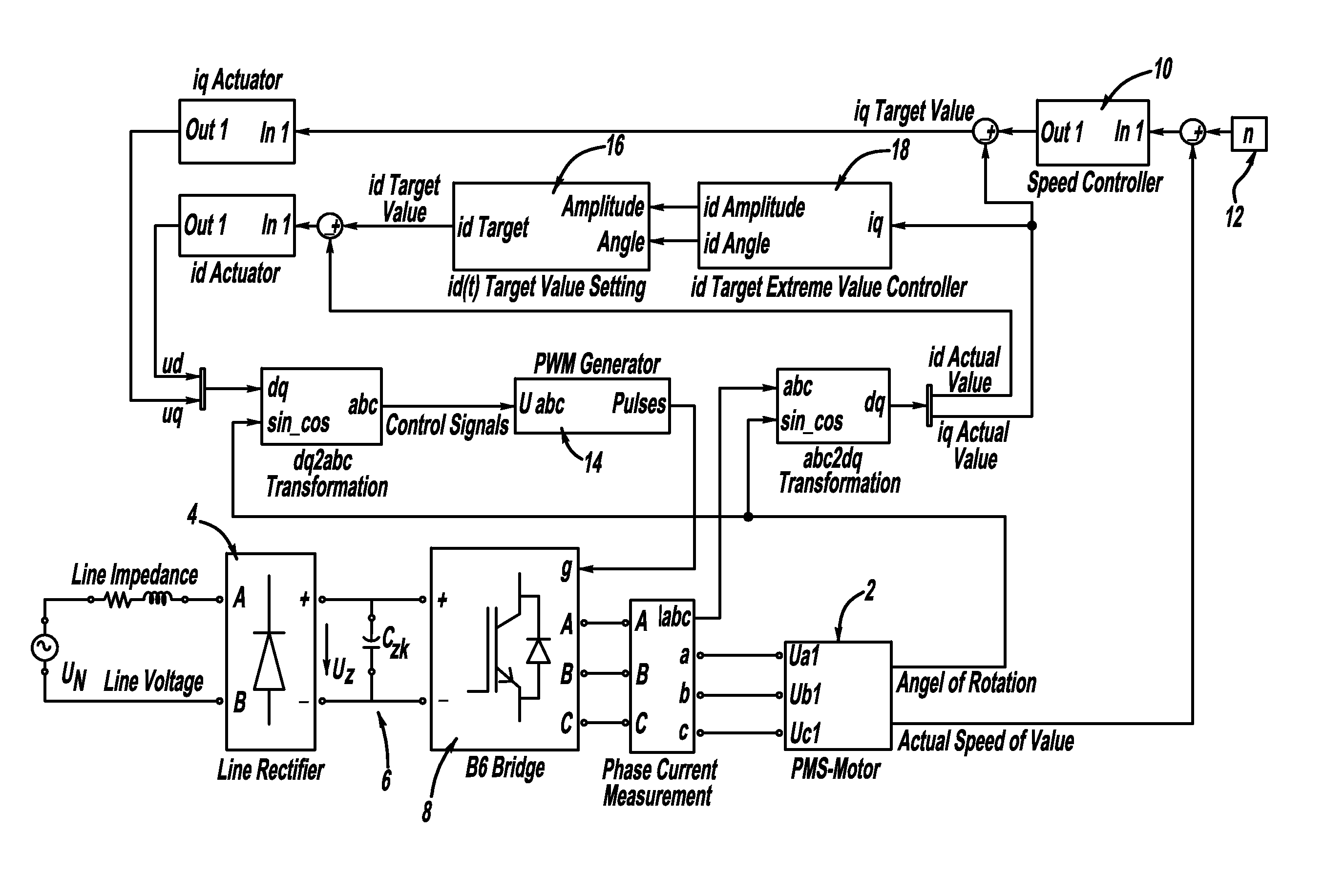
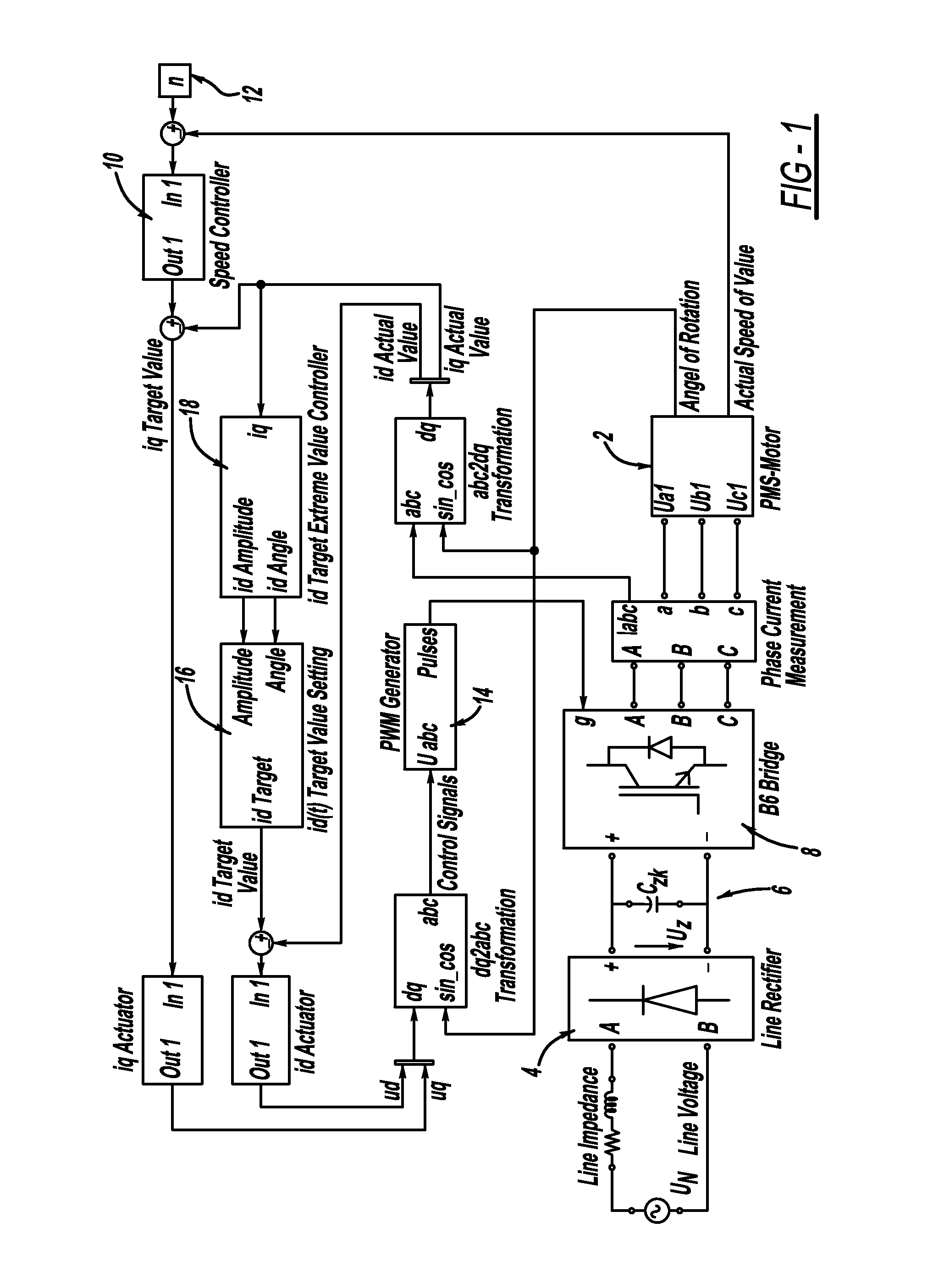
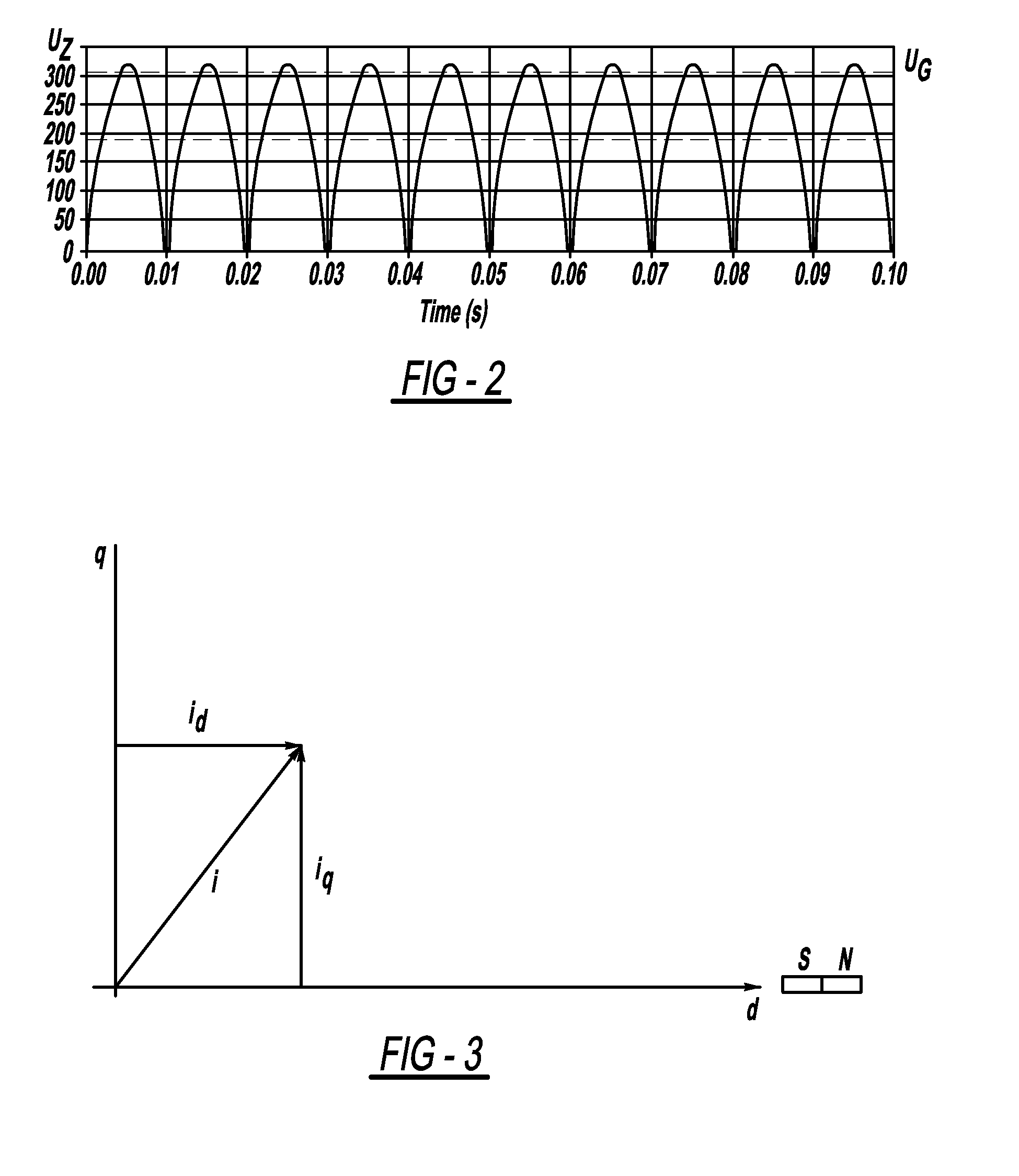
[0021]As is apparent from FIG. 1, a control system according to the present invention for controlling a collector-less, permanent magnet electronically commutated (EC) synchronous electric motor 2 consists of a supply or main rectifier 4, an downstream slender intermediate circuit 6 which contains no or only a minimum intermediate circuit reactance as well as an inverter 8 which is powered via the intermediate circuit 6 and can be applied for commutating the electric motor 2. By means of the main rectifier 4, which is illustrated in a simplified manner but designed as a full bridge, a single-phase mains AC voltage UN at a supply or main frequency fN is rectified into a strongly pulsating intermediate circuit voltage U. This intermediate circuit voltage Uz is illustrated in FIG. 2; it pulsates at twice the main frequency 2fN between zero and a peak value. The voltage profile corresponds to the value of the sinusoidal main AC voltage UN.

[0022]According to FIG. 1, the intermediate circ...


PUM


Abstract

The present invention relates to a method and a system for controlling a permanent magnet excited, brushless, electronically commutated, three-phase electric motor (2) wherein a single-phase main AC voltage (UN) having a mains frequency (fN) is rectified and supplied to an inverter (8) via a slender intermediate circuit (6) containing no, or minimum, intermediate circuit reactance as intermediate circuit voltage (Uz) pulsating at double the mains frequency (2fN) which is actuated for powering and commutating the electric motor (2). Control takes place by means of a field-oriented current-space vector regulator, wherein a q-current (iq) as torque-forming component of the current-space vector (i) is regulated perpendicularly to the permanent magnetic field and a d-current (id) can be regulated as a field-influencing component of the current-space vector (i) in the direction of the permanent magnet field. In this case, dynamic field attenuation occurs, wherein the d-current (id) in the negative range is defined with a sinusoidal profile and at double the main frequency (2fN) and wherein the d-current (id) is regulated according to its phase position and its amplitude such that ripple of the q-current (iq) is minimized. Since the q-current as torque forming component is proportional to the torque, thus the torque ripple is also minimized, in spite of the strongly pulsating intermediate circuit voltage (Uz).

Description

CROSS REFERENCE TO RELATED APPLICATION[0001]This application claims priority to European Patent Application No. EP 09165817.9, filed Jul. 17, 2009.FIELD OF THE INVENTION[0002]The present invention primarily relates to a method for controlling a permanent magnet excited, brushless, electronically commutated, in particular a three-phase electric motor wherein a single-phase, mains AC voltage having a supply or main frequency is rectified and supplied to an inverter via a slender intermediate circuit containing a minimum or no intermediate circuit reactance as intermediate circuit voltage pulsating at twice the main frequency, the inverter being actuated for powering and commutating the electric motor, wherein the actuation is carried out by means of a field-oriented current-space vector regulator (vector control), wherein a q-current as torque-forming component of the current-space vector is regulated perpendicularly to the permanent magnetic field and a d-current can be regulated as ...

Claims


Application Information

Patent Timeline
IPC IPC(8): H02P21/00
CPCH02M5/458H02M2007/53876H02P25/021H02P21/00H02P21/06H02P6/10H02P25/024H02M7/53876
Inventor WYSTUP, RALPHLIPP, HELMUT
Owner HUNTER DOUGLAS INC
Why Eureka
Try Eureka