Photovoltaic unit, a dc-dc converter therefor, and a method of operating the same

Inactive Publication Date: 2011-02-10
NXP BV
View PDF11 Cites 162 Cited by
  • Summary
  • Abstract
  • Description
  • Claims
  • Application Information

AI Technical Summary

Benefits of technology

[0011]It is an object of the present invention to provide a photovoltaic unit in which

Problems solved by technology

In practical cases, differences will exist between photogenerated currents, and output powers, of individual solar cells in the various modules, e.g. due to (part of) the modules being temporarily shaded, pollution on one or more solar cells, or even spread in solar cell behaviour—for instance due to manufacturing variations or to differences in the rate of degradation of performance of cells during aging.
Due to the current-source type behaviour of solar cells and their series connection these differences can lead to a relatively large drop in output power coming

Method used


Image

  • Photovoltaic unit, a dc-dc converter therefor, and a method of operating the same
  • Photovoltaic unit, a dc-dc converter therefor, and a method of operating the same
  • Photovoltaic unit, a dc-dc converter therefor, and a method of operating the same

Examples


Embodiment Construction

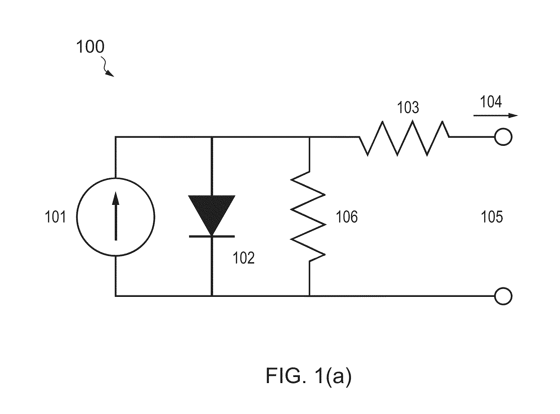
[0043]FIG. 1 shows the equivalent circuit 100 which is most often used to model the performance of a solar cell (the so-called single-diode model). A current source 101 corresponding to the photo-generated current (also referred to hereinafter as insolation current) Iins is in parallel with a diode 102 and shunt (that is, parallel) resistance Rp at 106. That part of Iins which does not flow through the diode or shunt resistance flows to an output node via the low-ohmic series resistance Rs 103 (typically a few mΩ per cell). Some internal leakage occurs via the high-ohmic shunt resistance Rp (typically in a kΩ to MΩ range).

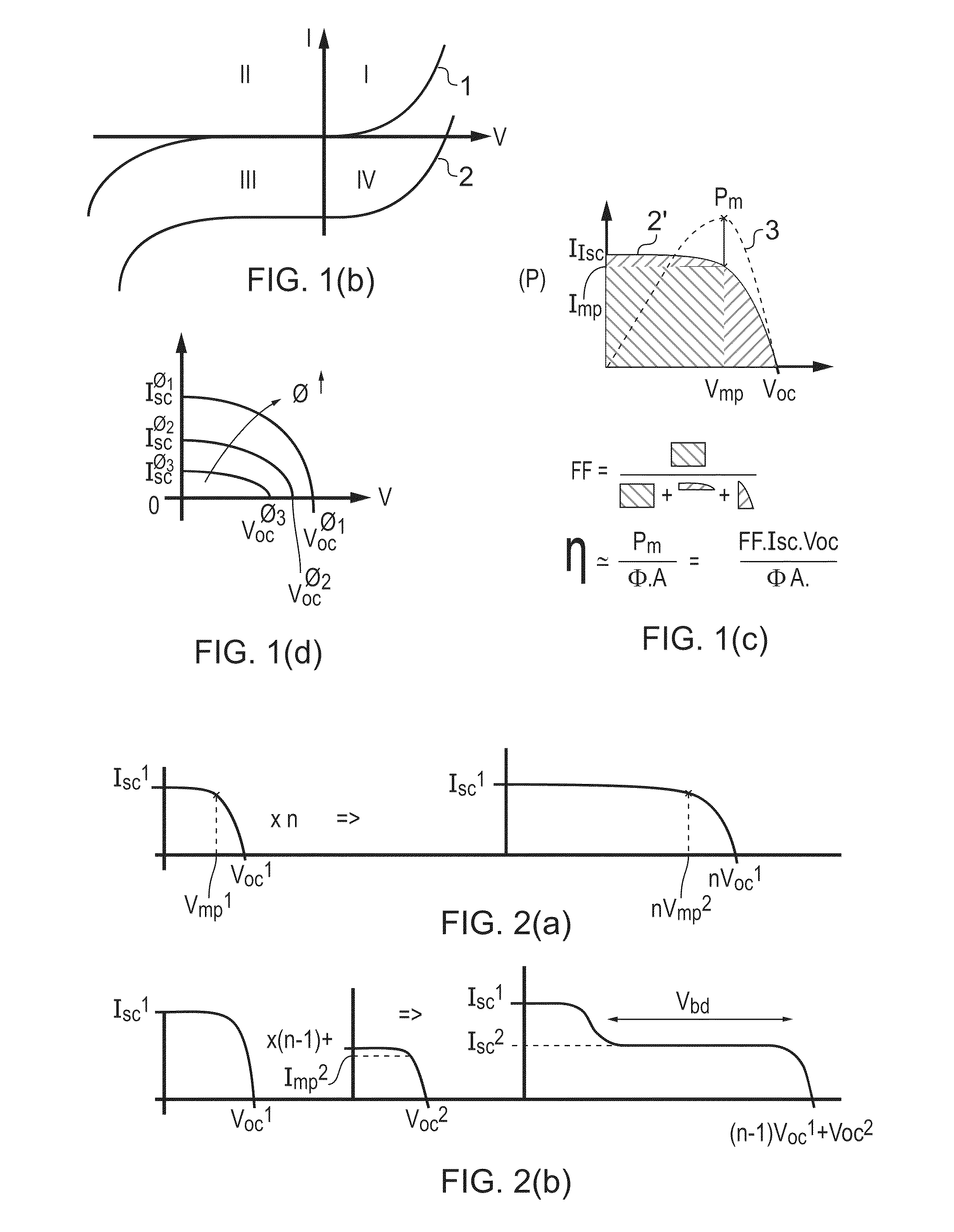
[0044]Its accompanying I-V characteristic is shown in FIG. 1b, for the case where the photo-generated current Iins is zero (curve 1) corresponding to no irradiation, and non-zero (curve 2) corresponding to an irradiated cell. As shown in the un-irradiated case, the IV characteristic is that of a diode with shunt and series resistances, and lies in the first and thi...


PUM


Abstract

A photovoltaic unit is disclosed comprising a plurality of sub-units connected in series, each sub-unit having a main input and a main output, which main output is connected to the respective main input of a neighbouring sub-unit, each sub-unit further comprising a segment comprising one or more series-connected solar cells, and a supplementary power unit, wherein the supplementary power unit is configured to at least one of receive power from or supply power to the neighbouring sub-unit. The supplementary power unit is preferably a DC-DC converter, and arranged to exchange energy between neighbouring segments, without requiring a high-voltage connection across the complete string (of more than 2 segments). The converter may be inductive or capacitive.
A DC-DC converter configured for use in such a unit is also disclosed, as is a method of controlling such a photovoltaic unit.

Description

FIELD OF INVENTION[0001]This invention relates to photovoltaic units and to methods of operating photovoltaic units.BACKGROUND OF INVENTION[0002]A photovoltaic cell (hereinafter also referred to as a solar cell) is a device which directly converts light such as sunlight into electricity. A typical such device is formed of a p-n junction in a semiconductor material. In operation, one surface of the device is exposed to light typically through an anti-reflective coating and protective material such as glass. Contact to this surface is made by a pattern of conductive fingers typically of a metal such as aluminium. Electrical contact to the other side of the p-n junction is typically provided by a continuous metal layer.[0003]Photovoltaic (PV) systems, typically made of several hundreds of solar cells, are increasingly used to generate electrical energy from solar energy falling on solar modules, hereinafter also referred to as solar panels. Generally, each solar module is formed by pla...

Claims


Application Information

Patent Timeline
IPC IPC(8): H02J1/00
CPCH01L31/02021Y02E10/566H02J7/35Y02E10/56
Inventor BUTHKER, HENRICUS CORNELIS JOHANNESDE WAAL, KLAASBERGVELD, HENDRIK JOHANNESHOOGZAAD, GIANSCHOOFS, FRANCISCUS A. C. M.
Owner NXP BV
Why Eureka
Try Eureka