

System and method for sulfur recovery
a sulfur recovery and sulfur technology, applied in the field of system and process for sulfur recovery, can solve the problem that the equations may not accurately represent the stoichiometry of the reaction
- Summary
- Abstract
- Description
- Claims
- Application Information
AI Technical Summary
Benefits of technology
Problems solved by technology
Method used
Image

Examples
Embodiment Construction
[0016]In the following specification and the claims that follow, the singular forms “a”, “an” and “the” include plural referents unless the context clearly dictates otherwise. The term “sulfur” as used in the specification refers to elemental sulfur, sulfur compounds or combination thereof, unless explicit mention of elemental sulfur is provided.
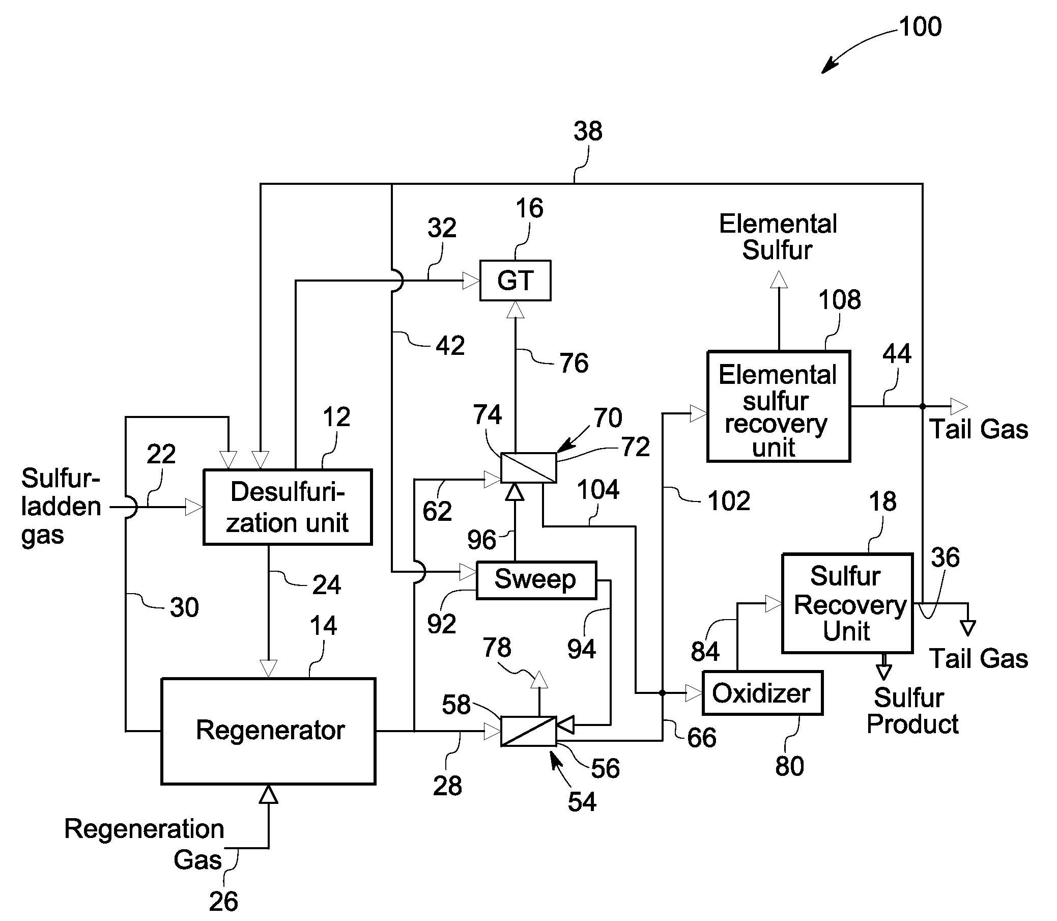
[0017]Various embodiments of the present invention describe a system and process for recovering sulfur from a sulfur stream desorbed from a sulfurized mass in a regenerator. The sulfur may be recovered as elemental sulfur or any compounds of sulfur such as sulfuric acid, ammonium sulfate, or organosulfur compounds.
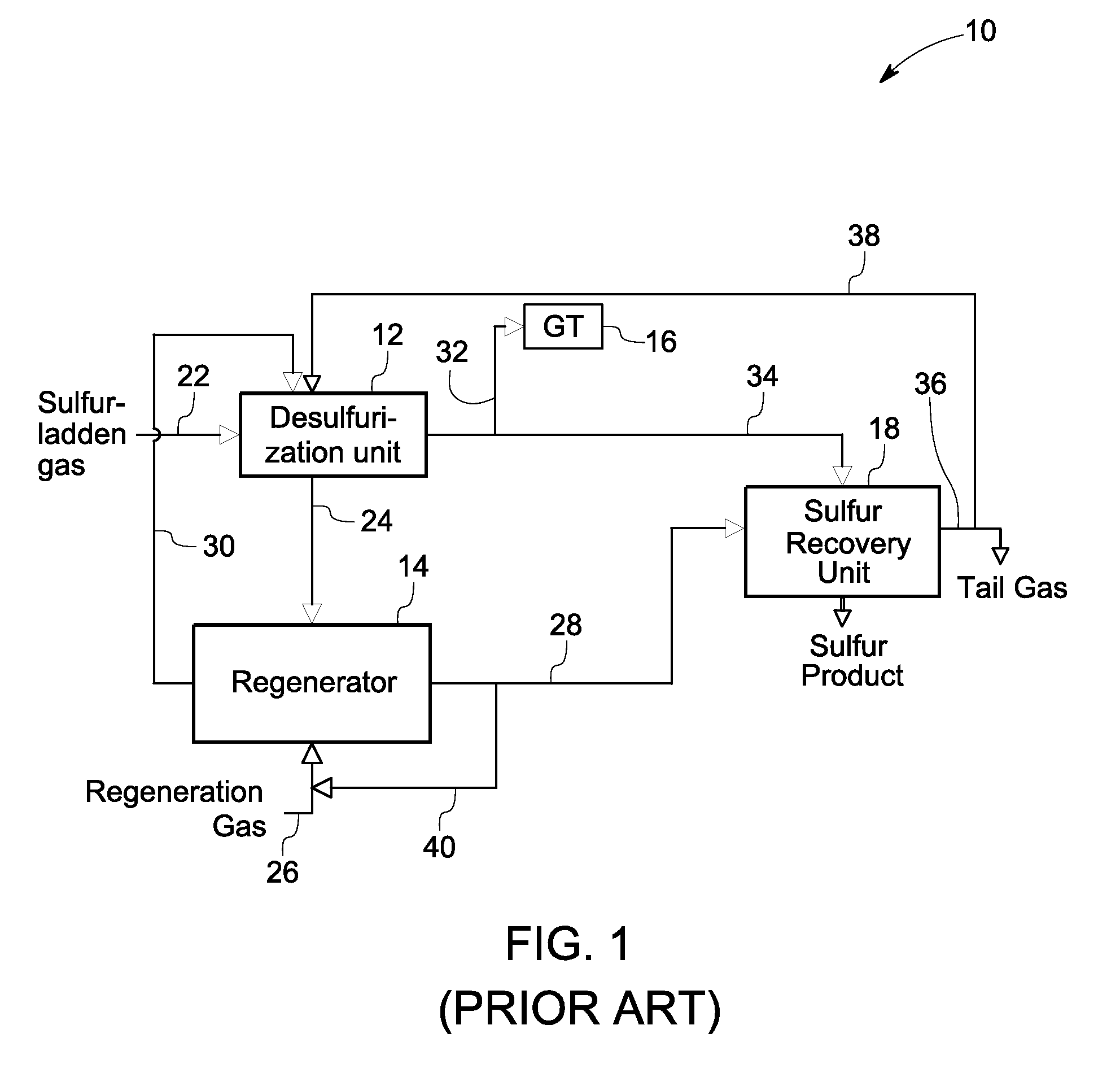
[0018]FIG. 1 is a diagrammatical view of a prior art sulfur recovery system 10. The system 10 includes a desulfurization unit 12, a regenerator 14, and a sulfur recovery unit 18. During operation, a sulfur-laden gas stream from a gasifier enters the desulfurization unit 12 through a sulfur-laden gas track 22 and contacts a sorbent ...
PUM
| Property | Measurement | Unit |
|---|---|---|
| mass | aaaaa | aaaaa |
| concentration | aaaaa | aaaaa |
| electrical power | aaaaa | aaaaa |
Abstract
Description
Claims
Application Information