Supercharged boost-assist engine brake

a technology of engine brake and supercharger, which is applied in the field of vehicles, can solve the problems of engine delta p (i.e., engine delta minus intake manifold pressure), and engine retarding power can be reduced, so as to enhance engine retarding power, increase peak cylinder pressure, and increase the effect of peak cylinder pressur

Active Publication Date: 2011-02-17
INT ENGINE INTPROP CO LLC
View PDF26 Cites 27 Cited by
  • Summary
  • Abstract
  • Description
  • Claims
  • Application Information

AI Technical Summary

Benefits of technology

The exemplary apparatus and methods of the invention provide a control system for engine braking for a vehicle powered by a turbocharged engine. The apparatus and methods of the invention utilize a “supercharger” to boost turbocharger air flow. In an engine having a plurality of cylinders and an intake valve and an exhaust valve associated with each of the cylinders, wherein the intake valve opens the cylinder to an intake manifold and the exhaust valve opens the cylinder to an exhaust manifold, the control system includes an engine braking control and a “supercharger” in the form of an engine driven air pumping device operable during engine braking by command of the engine braking control to increase the flow of compressed air into the intake manifold.
In any compression-release engine brake, as long as an efficient or appropriate braking valve event (lift) occurs at the braking TDC, in general, engine retarding power will increase with increasing peak cylinder pressure. The described embodiments and methods are particularly useful for heavy duty EVBec engine brakes or bleeder brakes. The described embodiments and methods enhance engine retarding power—through delivery of high boost pressure air to the intake manifold and hence high peak cylinder pressure.
By using supercharged boost assist, engine retarding power increases significantly through a combination of enhanced compression-release effect and increased parasitic power to drive the supercharger. Engine air flow rate increases. Injector tip temperature decreases. Engine transient torque and emissions such as soot and smoke performance improves.
If the air pumping device feeds boost air at the turbocharger compressor inlet, a check valve or two-way control valve can be used before the mixing point to prevent reverse flow to the ambient. If the air pumping device feeds boost air at turbocharger compressor outlet, a check valve or two-way control valve can be used before the mixing point to prevent reverse flow to the turbocharger compressor. Another check valve may be used as needed at the outlet of the air pumping device in order to prevent reverse flow to the air pumping device during engine firing operation or during braking operation when reverse pulse is high. When an electronically controlled two-way valve is used, its leakage of the reverse flow may be less than the leakage of the passive check valve.
Under some circumstances, during firing operation, engine transient performance (torque and soot / smoke reduction) may be improved significantly if the supercharged boost assist system is activated.

Problems solved by technology

Also, engine delta P (i.e., exhaust manifold pressure minus intake manifold pressure) and exhaust manifold pressure may become undesirably high.
As a result, the compression-release effect can be weakened, retarding power can be reduced, and in-cylinder component (e.g. fuel injector tip) temperature can become undesirably high.
For the EVBec engine brake, there may be difficulties controlling the braking valve timing of the secondary valve lift event and difficulty controlling the compressor efficiency to deliver high intake manifold boost pressure.

Method used


Image

  • Supercharged boost-assist engine brake
  • Supercharged boost-assist engine brake
  • Supercharged boost-assist engine brake

Examples


Embodiment Construction

While this invention is susceptible of embodiment in many different forms, there are shown in the drawings, and will be described herein in detail, specific embodiments thereof with the understanding that the present disclosure is to be considered as an exemplification of the principles of the invention and is not intended to limit the invention to the specific embodiments illustrated.

In any compression-release engine brake, as long as an efficient or appropriate braking valve event (lift) occurs at the braking TDC, in general, engine retarding power will increase with increasing peak cylinder pressure.

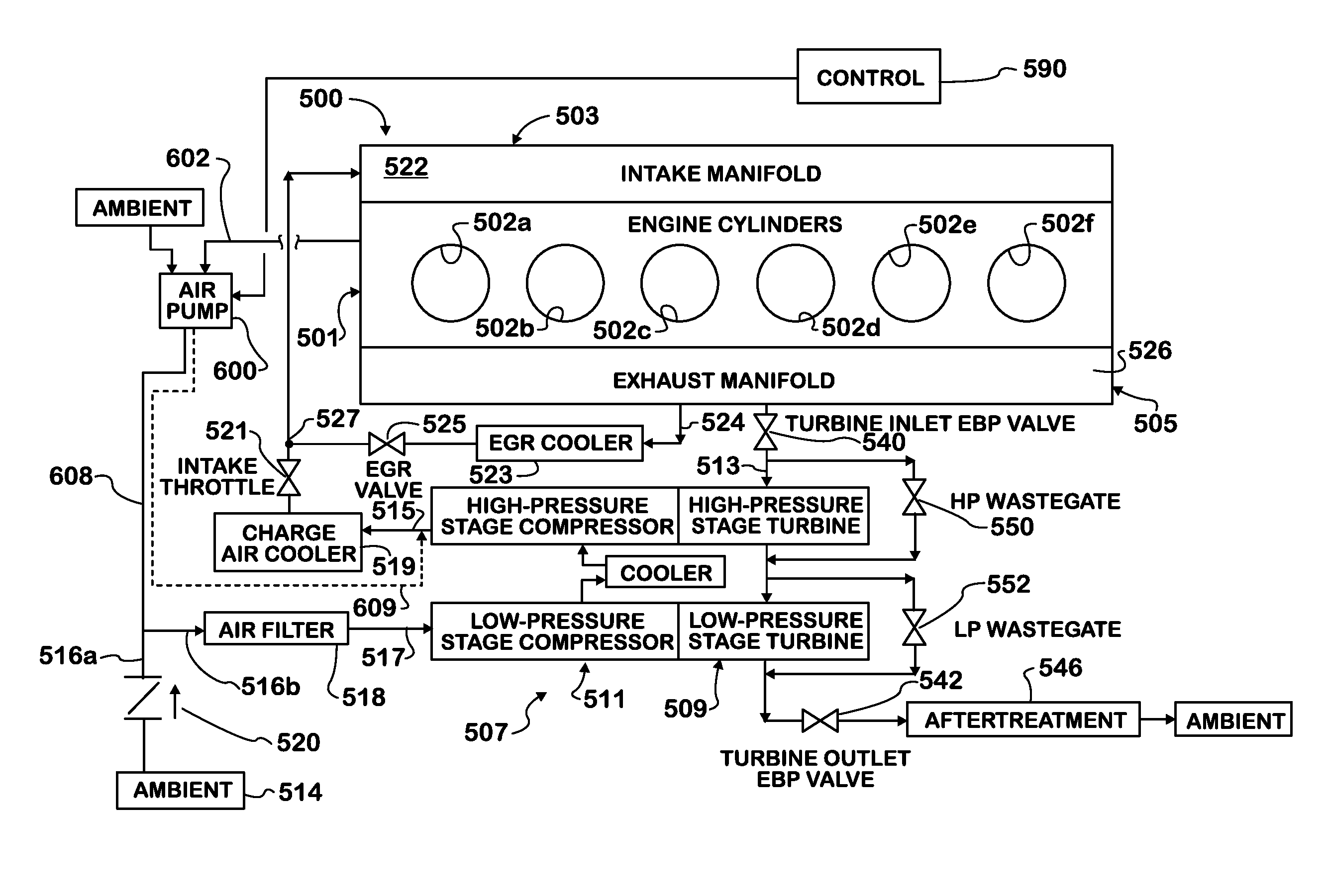
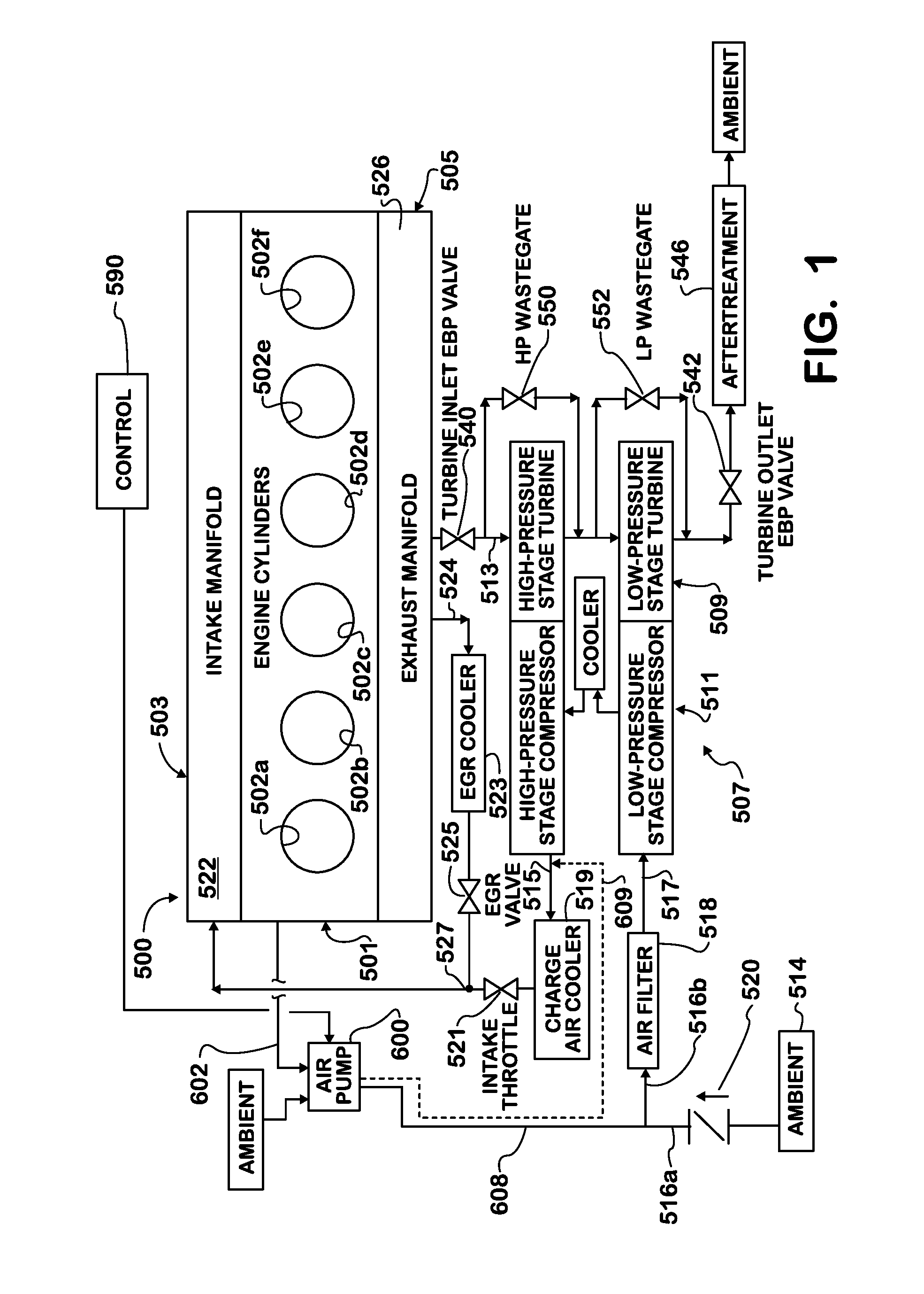
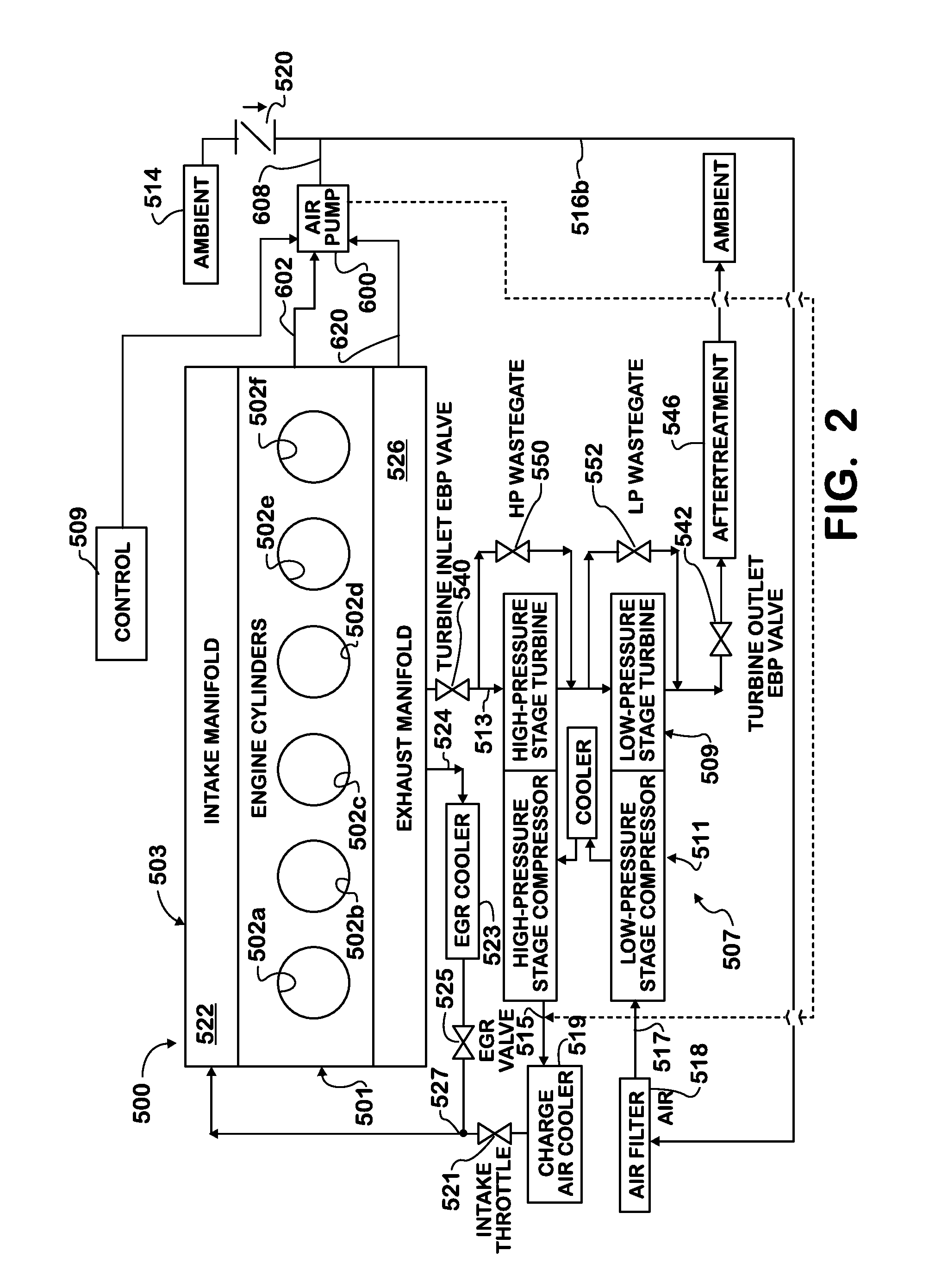
In compression-release engine brakes, the retarding power consists of two parts: the compression-release effect and the contribution from pumping loss. The pumping loss consists of the contributions from engine delta P, mainly related to turbine effective area, and engine volumetric efficiency, mainly affected by valve timing / event. The compression-release effect is related to the exh...


PUM


Abstract

A control system for engine braking for a vehicle powered by a turbocharged engine uses a supercharger to assist a turbocharger compressor to boost turbocharger air flow into the engine cylinders. An engine driven air pumping device draws ambient air, or alternately exhaust gas through the pump inlet, compresses the air, and delivers the compressed air through the pump outlet to the turbocharger compressor inlet or alternately the turbocharger compressor outlet. The increased air flow into the cylinders and out of the cylinder exhaust valves increases retarding power of the vehicle.

Description

TECHNICAL FIELDThis disclosure relates to vehicles, particularly large tractor trailer trucks, including but not limited to apparatus, control and operation for engine braking.BACKGROUNDAdequate and reliable braking for vehicles, particularly for large tractor-trailer trucks, is desirable. While drum or disc wheel brakes are capable of absorbing a large amount of energy over a short period of time, the absorbed energy is transformed into heat in the braking mechanism.Braking systems are known which include exhaust brakes which inhibit the flow of exhaust gases through the exhaust system, and compression release systems wherein the energy required to compress the intake air during the compression stroke of the engine is dissipated by exhausting the compressed air through the exhaust system.In order to achieve a high engine-braking action, a brake valve in the exhaust line may be closed during braking, and excess pressure is built up in the exhaust line upstream of the brake valve. Fo...

Claims


Application Information

Patent Timeline
Patent Type & Authority Applications(United States)
IPC IPC(8): F02D23/00
CPCF02B29/0412F02B37/013F02D9/06F02D13/04F02D23/00Y02T10/42F02D41/0007F02D2250/34F02M25/0711F02M25/0727Y02T10/144F02D41/0005F02M26/08F02M26/23Y02T10/12Y02T10/40
Inventor XIN, QIANFANZIELKE, MARTIN R.BARTKOWICZ, MICHAEL D.CATTANI, LUIS CARLOSGRAVANTE, STEVEPROCHNAU, TIMOTHYCALASH, ANTOUN Y.CAGNEY, JOHN L.
Owner INT ENGINE INTPROP CO LLC
Why Eureka
Try Eureka