
Thermal vapor stream apparatus and method

a technology of thermal vapor stream and apparatus, which is applied in the direction of lighting and heating apparatus, machines/engines, and well accessories, etc., can solve the problems of difficult to use high pressure thermal vapor stream for other applications, such as cogeneration of electricity and heat, and obtain, operate and maintain equipment. , to achieve the effect of facilitating injection of high pressure thermal vapor stream, enhancing the recovery of viscous petroleum, and increasing the transfer of latent hea

Inactive Publication Date: 2011-02-17
EOR TECH HLDG INC
View PDF31 Cites 12 Cited by
  • Summary
  • Abstract
  • Description
  • Claims
  • Application Information

AI Technical Summary

Benefits of technology

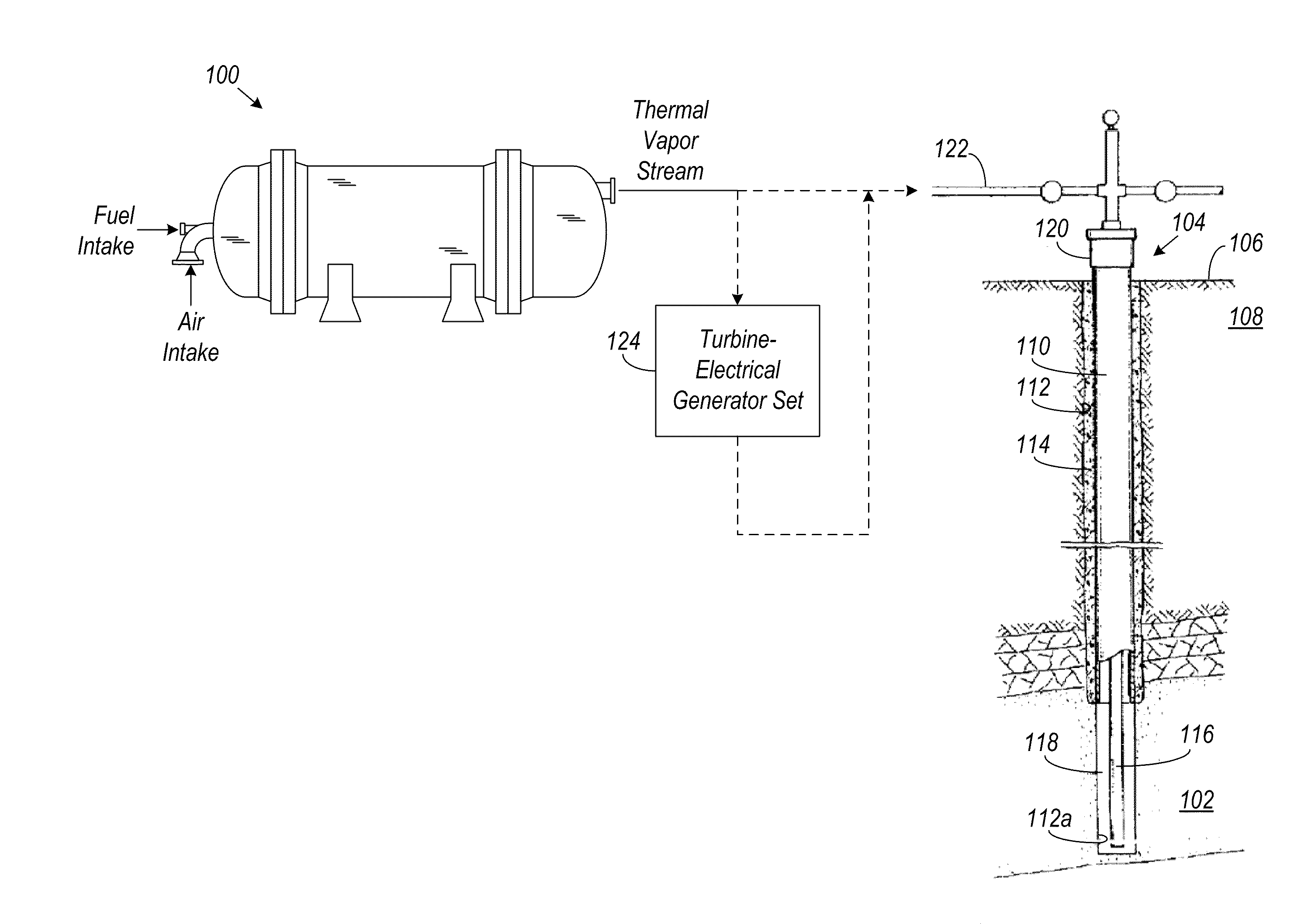
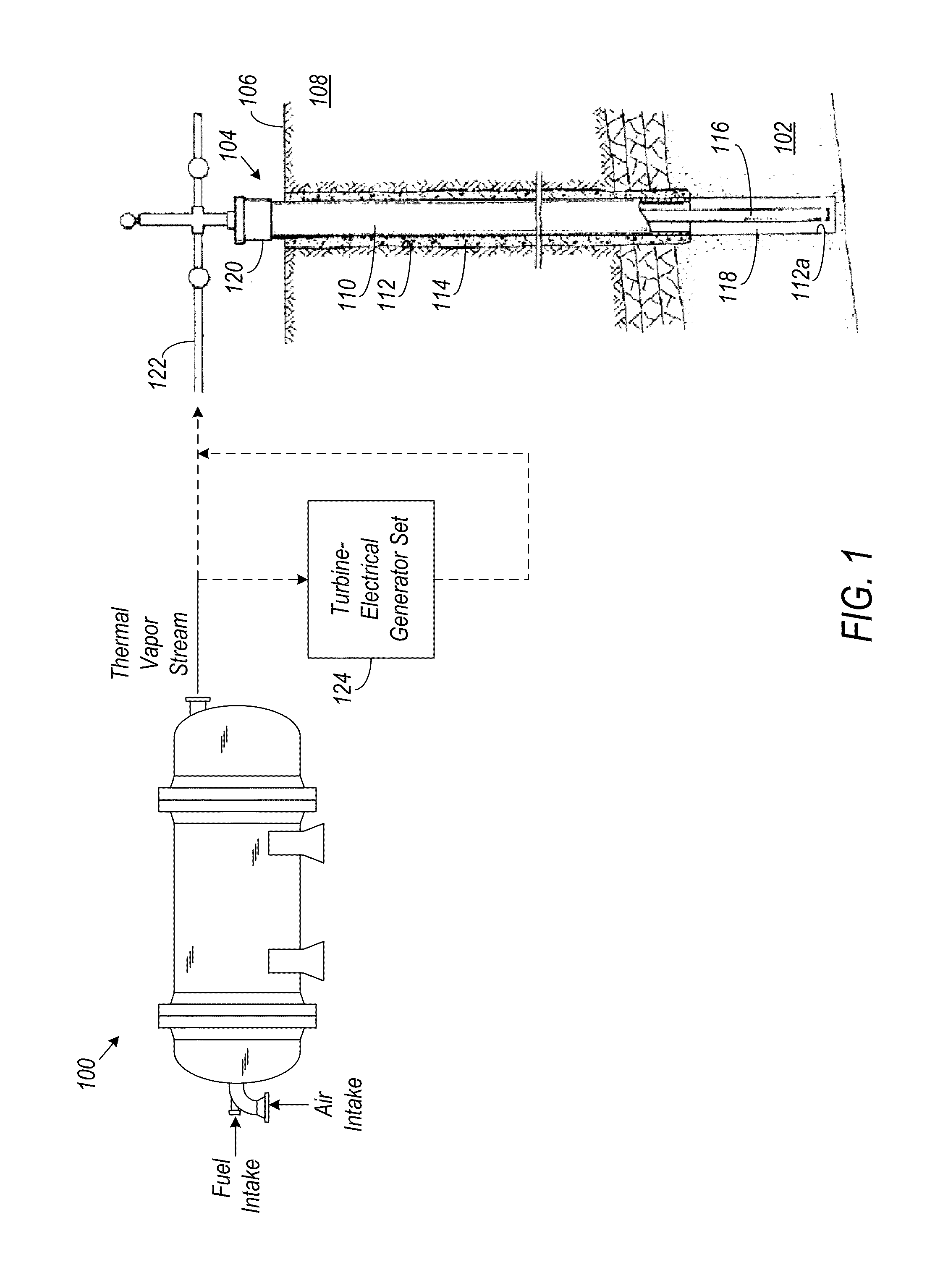
[0007]Aspect of the invention relate to a low emission and environmentally friendly apparatus and method for generating a high pressure thermal vapor stream. Such an apparatus and method may be used for recovering highly viscous petroleum from a subterranean formation, cogeneration of electricity and heat, and the like. The apparatus and method of the invention facilitate injection of a high pressure stream of thermal vapor comprising superheated steam, carbon dioxide, and nitrogen. In a subterranean formation, the high pressure thermal vapor stream may be used to enhance recovery of viscous petroleum. The superheated steam increases the transfer of latent heat throughout the formation, the carbon dioxide forms a miscible interface with the hydrocarbon in the petroleum and also reduces the viscosity of the petroleum, while the nitrogen migrates into the formation to create a gas drive for the petroleum. Solvents and other surfactants may also be added to the superheated steam to increase recovery of the petroleum from the formation.
[0008]The high pressure stream of thermal vapor may be generated by burning a high temperature fuel, such as diesel, crude oil, diesel-crude mixture, kerogen, coal powder, and other short and long chain hydrocarbon products in an enclosed jet vapor system. The fuel is preferably atomized such that it is in the form of a fine mist for improved combustion.
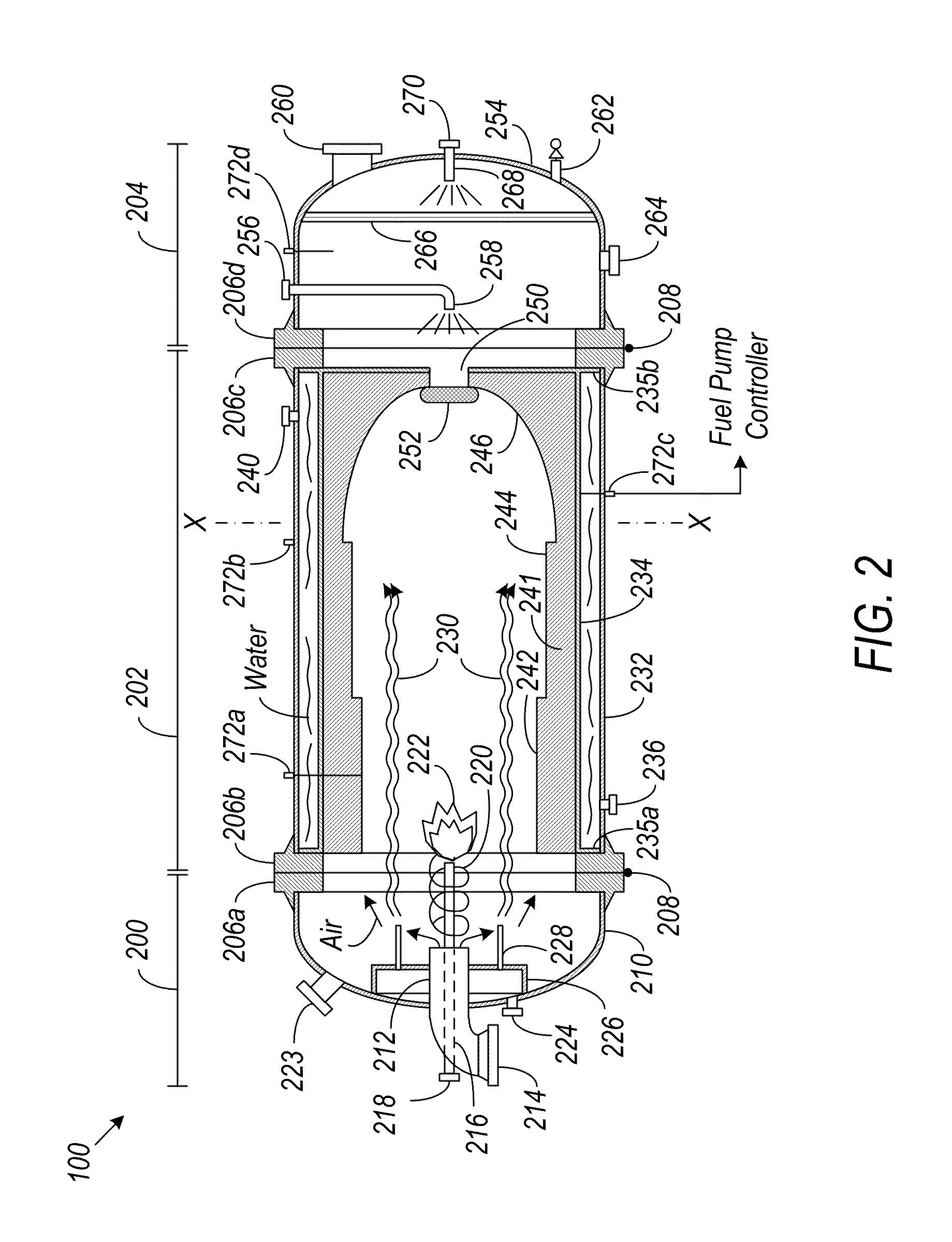
[0009]A removable, preformed refractory composed of multiple sections may be provided in some embodiments on the interior of the jet vapor system to help withstand the temperature in the jet vapor system. The refractory sections may have different thicknesses that create turbulence in the combustion gases to improve heat distribution in the jet vapor system. Because the high temperatures involved can limit the life of the refractory, in some embodiments, the refractory may be in the form of a unitary cartridge that may be easily and frequently removed from the jet vapor system and replaced as needed.
[0010]A cone or curtain of water may be formed around the flame produced by the combustion of the high temperature fuel in some embodiments to help lower the temperature of the refractory without lowering the temperature of the flame.
[0011]Water may then be introduced directly onto the combustion gases to create superheated steam or vapor. Various ways may be used to introduce the water onto the combustion gases, including spraying, weeping, dripping, and the like. A high temperature catalytic converter may be used to minimize emissions from the combustion process, and various corrosion-controlling chemicals may be added to the water to facilitate removal of any sulfur oxides or nitrogen oxides.

Problems solved by technology

Because of the high volumes, pressures, and temperatures involved, difficulties often arise in obtaining, operating and maintaining the equipment and apparatuses needed for generating the required amounts of combustion gases that will produce the required amounts of steam under sufficiently high pressures and temperatures to provide satisfactory economic recovery of the highly viscous petroleum.
For example, existing apparatuses that are capable of generating a suitable high pressure thermal vapor stream tend to be large, heavy, and complex, and typically emit gases that are not very environmentally-friendly, all of which may result in additional costs to the petroleum recovery process.
The environmentally harmful emissions of conventional equipment also make it difficult to use the high pressure thermal vapor stream for other applications, such as cogeneration of electricity and heat.

Method used


Image

  • Thermal vapor stream apparatus and method
  • Thermal vapor stream apparatus and method
  • Thermal vapor stream apparatus and method

Examples


Embodiment Construction

[0021]The drawings described above and the written description of specific structures and functions below are not presented to limit the scope of what has been invented or the scope of the appended claims. Nor are the drawings drawn to any particular scale or fabrication standards, or intended to serve as blueprints, manufacturing parts list, and the like. Rather, the drawings and written description are provided to teach any person skilled in the art to make and use the inventions for which patent protection is sought. Those skilled in the art will appreciate that not all features of a commercial embodiment of the inventions are described or shown for the sake of clarity and understanding.

[0022]Persons of skill in this art will also appreciate that the development of an actual commercial embodiment incorporating aspects of the inventions will require numerous implementation-specific decisions to achieve the developer's ultimate goal for the commercial embodiment. Such implementatio...


PUM


Abstract

A low emission and environmentally friendly apparatus and method is used to generate a high pressure stream of thermal vapor. The thermal vapor stream may be injected into a subterranean formation for recovery of highly viscous petroleum or used to turn a steam turbine for driving an electrical generator. In one implementation, the high pressure stream of thermal vapor is generated by burning a high temperature fuel, including any short or long chain hydrocarbon products from methane to coal, in an enclosed vessel to produce combustion gases. Various techniques may be used to improve heat distribution and lower the temperature of the combustion gases. Water may be used to quench the combustion gases and produce the superheated steam or vapor. The water may be introduced onto the combustion gases by spraying, weeping, dripping, and the like.

Description

CROSS REFERENCE TO RELATED APPLICATIONS[0001]Not ApplicableTECHNICAL FIELD OF THE INVENTION[0002]Aspects of the invention relate generally to the use of a thermal vapor stream for cogeneration of electricity and heat and desirable gases, and for recovery of petroleum from a subterranean formation. More particularly, aspects of the invention relate to new and improved apparatuses and methods for producing a high pressure thermal vapor stream that may be injected into the subterranean formation for recovering heavy viscous petroleum, or for sequestering the gases of combustion while producing electricity.BACKGROUND OF THE INVENTION[0003]Successful recovery of highly viscous petroleum using a high pressure thermal vapor stream typically involves production of hot combustion gases that are flowed into a steam generating device to produce large quantities of high pressure thermal vapor or steam. The high pressure thermal vapor or steam is thereafter injected into a subsurface formation t...

Claims


Application Information

Patent Timeline
IPC IPC(8): F02C3/30F22B27/16E21B43/24
CPCE21B43/24Y02E20/14F22B1/26F01K21/047
Inventor KRAJICEK, RICHARD W.
Owner EOR TECH HLDG INC
Learn More