
Guiding spray droplets into an inlet capillary of a mass spectrometer

a mass spectrometer and droplet technology, applied in the direction of instruments, particle separator tube details, separation processes, etc., can solve the problems of both droplet charges falling below the rayleigh limit, the inability of the jet to be manipulated, and the inlet charge of the droplet to be split, so as to prevent the evaporation of droplets before the end of the evaporation period, improve gas throughput, and improve the effect of focusing

Active Publication Date: 2011-02-17
BRUKER DALTONIK GMBH & CO KG
View PDF9 Cites 7 Cited by
  • Summary
  • Abstract
  • Description
  • Claims
  • Application Information

AI Technical Summary

Benefits of technology

[0024]The droplet source can be configured as an electrospray device, and the droplet sink can be configured as an inlet capillary. The spray droplets from the spray capillary should not be evaporated before they enter the inlet capillary. The cloud of droplets should also be fed into an entrance aperture of the inlet capillary as completely as possible, finely focused by the pseudopotentials of the droplet guide. The droplets are introduced into the inlet capillary since, as indicated above, the droplets can be guided through the capillary with low losses by Bernoulli focusing. Spray capillaries with liquid flow up to a few hundred microliters per minute can be used. The droplets should have a relatively small size before being directed into the inlet capillary in high numbers. The droplets should not, however, completely evaporate before being introduced into the inlet capillary.
[0025]In order to introduce substantially small, equi-sized droplets (e.g., with a diameter between 50 to 200 nanometers) into the inlet capillary, larger droplets should be retained in a drying gas longer than smaller droplets. This may be achieved by generating a flow of a hot drying gas and an opposing electric field in the droplet guide. The hot drying gas and the electric field are generated such that the smaller droplets move faster through the droplet guide towards the inlet capillary than do the larger droplets. If the droplets move relatively slowly through a moving drying gas, the mobility of droplets at the Rayleigh limit is proportional to the root of the diameter, and thus higher for larger droplets than for small droplets, an effect which can be utilized. The droplets retained longer in the droplet guide thus have more time to vaporize. The final evaporation of the spray droplets, however, should occur after the droplets have left the droplet guide (i.e., in the inlet capillary) because otherwise the analyte ions may be drawn to the electrodes of the droplet guide and be discharged.
[0027]After the droplets have been introduced into the inlet capillary, gas-dynamic focusing (Bernoulli focusing) directs the droplets for as long as possible along the axis of the inlet capillary. Premature complete evaporation of the droplets therefore should be prevented. The evaporation can be controlled by selecting the size of the droplets introduced and by controlling the humidity of the transport gas. The focusing may be enhanced by generating an opposing electric field in the inlet capillary.
[0028]The inlet capillary may be segmented into a plurality of segments such that a large proportion of the inflowing transport gas can be evacuated with small pumps at relatively high pressure. The droplets are guided between the segments using embodiments of the aforesaid droplet guide. A small quadrupole rod system, for example, can guide droplets from a first segment to an aperture of a second segment. New transport gas with a desired temperature and humidity can be fed into each new segment such that, for example, the droplets evaporate in the last segment. Such segmented inlet capillaries make it possible to select capillaries with larger internal diameters and, therefore, increase gas throughput. As a result, more droplets can be transported.

Problems solved by technology

The jet is intrinsically unstable due to its high surface charge, which opposes the surface tension.
The unstable surface brings about random oscillations of the fluid on the surface, for example, cause the droplets to split.
The separation of the droplets, however, causes the charges of both droplets to fall below the Rayleigh limit.
Both small and large droplets, however, have a mass-to-charge ratio above the Rayleigh limit and thus continue to vaporize.
Disadvantageously, the spray capillary tips used for nanospraying must be precisely adjusted with respect to the inlet capillary aperture.
However, very few of the analyte ions are directed into the admission aperture due to the large volume of analyte ions that are produced.
It is therefore difficult to draw a large number of analyte ions from the large volume into the inlet capillary.
The reduction in volume, however, further accelerates the spray droplets.
Although normal electrospraying ionizes most of the analyte molecules when the droplets are completely vaporized, the yield of ions introduced into the analyzer is relatively small.
Nanospraying, however, cannot typically be coupled with liquid chromatography without splitting the flow of liquid since nano-HPLC has flow rates which are far above those which nanospraying can cope with.
The unfavorable splitting of the liquid flow therefore cancels out the favorable ion yield.
Attempts to inject larger droplets, which are produced at slightly higher flow rates with slightly larger spray tip aperture diameters, directly into the inlet capillary have so far been unsuccessful.

Method used


Image

  • Guiding spray droplets into an inlet capillary of a mass spectrometer
  • Guiding spray droplets into an inlet capillary of a mass spectrometer
  • Guiding spray droplets into an inlet capillary of a mass spectrometer

Examples


Embodiment Construction

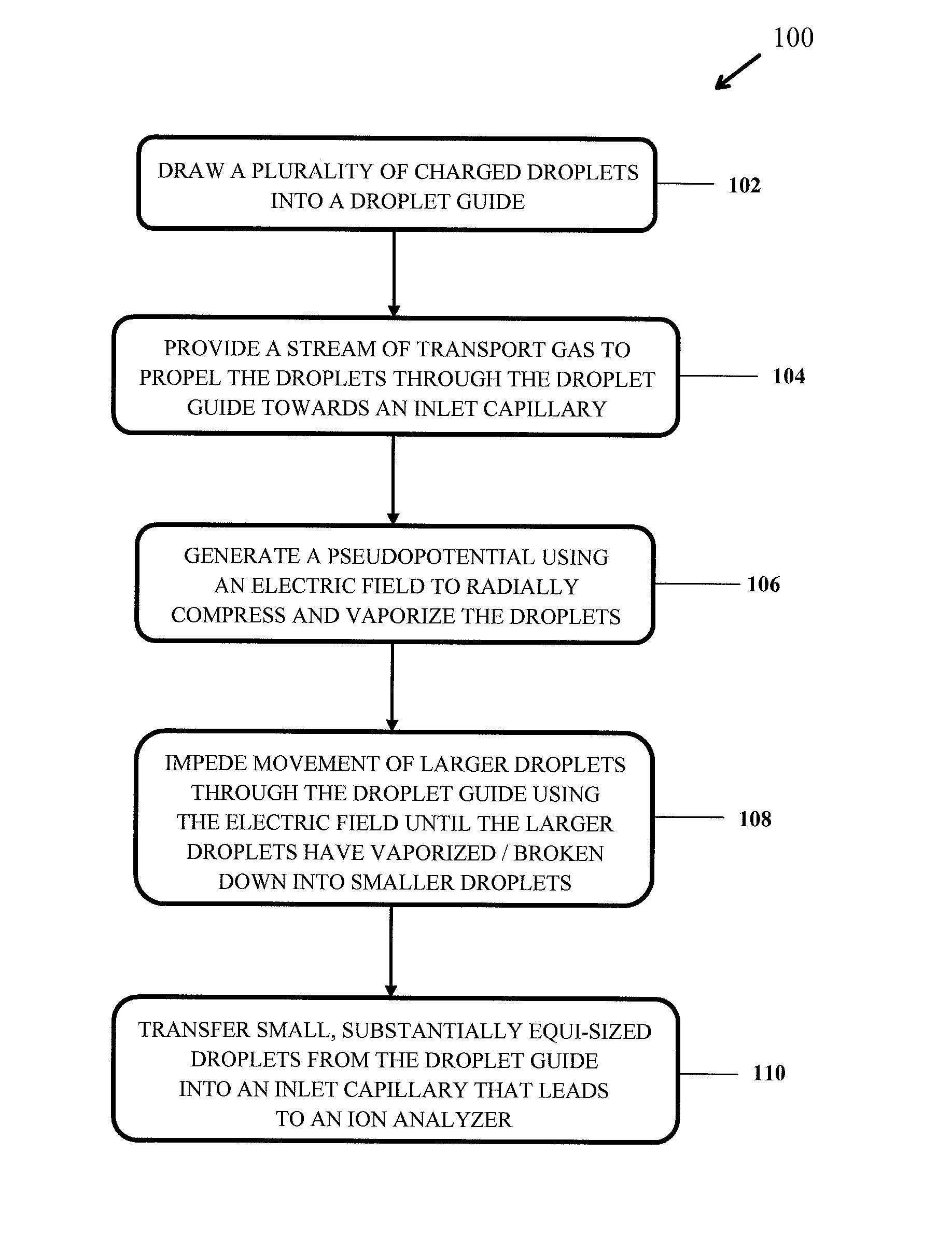
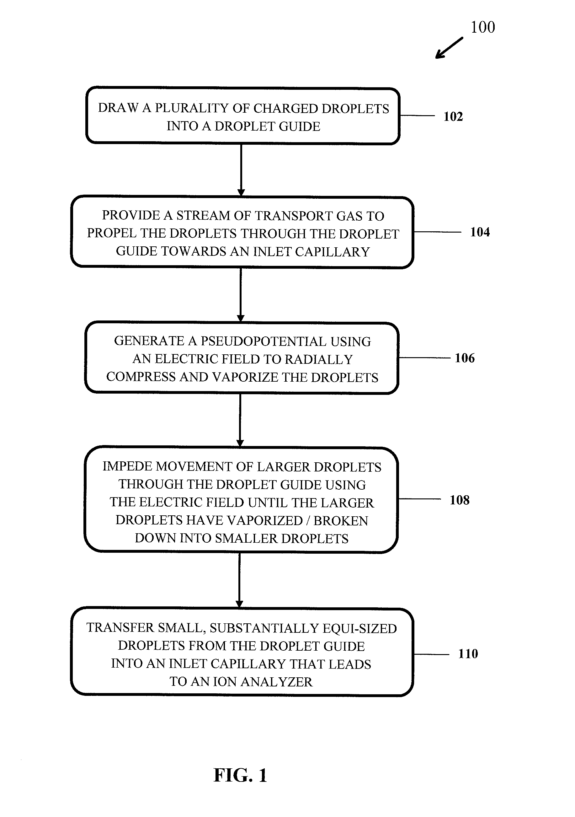
[0037]FIG. 1 illustrates a process 100 for forming a jet of droplets using a guiding device (also referred to below as a “droplet guide”). The jet of droplets is fowled by radially compressing a cloud of charged droplets received from a droplet source, and guiding the droplets along a predefined path to a droplet sink (see steps 102, 104 and 106). The droplets are compressed and guided by audio-frequency alternating voltages applied to electrodes in the guiding device. The term “droplet source” refers to the appearance of droplets at one point of a defined observation region. The term “droplet sink” refers to the disappearance of the droplets at a different point in the region observed.

[0038]The cloud of charged droplets is compressed by inhomogeneous alternating fields on the droplets; i.e., creating “pseudopotentials”. Pseudopotentials are generally known in the art and, therefore, will not be discussed in further detail. The jet of droplets can be compressed (or “focused”) by gen...


PUM


Abstract

Charged droplets are guided along a defined path from a droplet source to a droplet sink. A focusing pseudopotential distribution generated by audio frequencies on electrodes of a guiding device guide the charged droplets from the droplet source to the droplet sink with low loss. The droplets can be driven along the droplet guide by a gas flow, an axial electric field or a combination of both. For example, charged droplets from a spray capillary of an electrospray ion source at atmospheric pressure may be introduced into the inlet capillary leading to the vacuum system of ion analyzers, a procedure similar to that used up to now in nanoelectrospraying, but with substantially higher flow rates. In the guiding device, the droplets can be manipulated in different ways, for example evaporated down to a desired size. The introduction of small droplets into gas-aspirating capillaries is of interest because it is possible to keep the droplets on axis by Bernoulli focusing and to guide them in large quantities and with low loss through the capillary. The ability to guide the droplets makes it also possible to install a segmented inlet capillary with intermediate pumping, which allows pumping capacity to be saved. Advantageously, the sensitivity of ion analyzers such as mass spectrometers or ion mobility spectrometers by at least one order of magnitude.

Description

PRIORITY INFORMATION[0001]This patent application claims priority from German Patent Application No. 10 2009 037 715.8 filed on Aug. 17, 2009, which is hereby incorporated by reference.FIELD OF INVENTION[0002]The invention relates to the field of mass spectrometry, and in particular to guiding charged droplets along a defined path into a droplet sink such as, for example, an inlet capillary of a mass spectrometer.BACKGROUND OF THE INVENTION[0003]Ions may be generated from relatively heavy analyte molecules, having molecular weights of several hundred to several thousand Daltons, using an electrospray ion source. For example, a relatively high voltage (e.g., several kilovolts) may be applied to a pointed spray capillary, containing spray liquid with dissolved analyte molecules, to generate a relatively strong electric field around the tip. The electric field polarizes and charges the surface of the spray liquid in the open tip. In this manner, an electric tractive force creates a so-...

Claims


Application Information

Patent Timeline
IPC IPC(8): H01J49/04
CPCH01J49/062H01J49/0445
Inventor FRANZEN, JOCHENKOSTER, CLAUS
Owner BRUKER DALTONIK GMBH & CO KG
Learn More