Some wells may require well treatment, such as fracturing of the
wellbore if drilling and production activity have packed the wellbore surface to the extent that production has slowed.
As evident from these examples and as known in the art, the optimization of a production field is a complex problem, involving many variables and presenting many choices.
This problem is exacerbated by the complexity and inscrutability of the sub-surface “architecture” of today's producing reservoirs.
As mentioned above, current-day oil and gas reservoirs are often at extreme depths or in otherwise difficult geographical locations, both on land or offshore, because those reservoirs that are easy to reach have already been developed and produced.
These extreme depths and relative inaccessibility limit the precision and accuracy of the necessarily indirect methods used to characterize the structure and location of the
hydrocarbon-bearing reservoirs.
In addition, the sub-
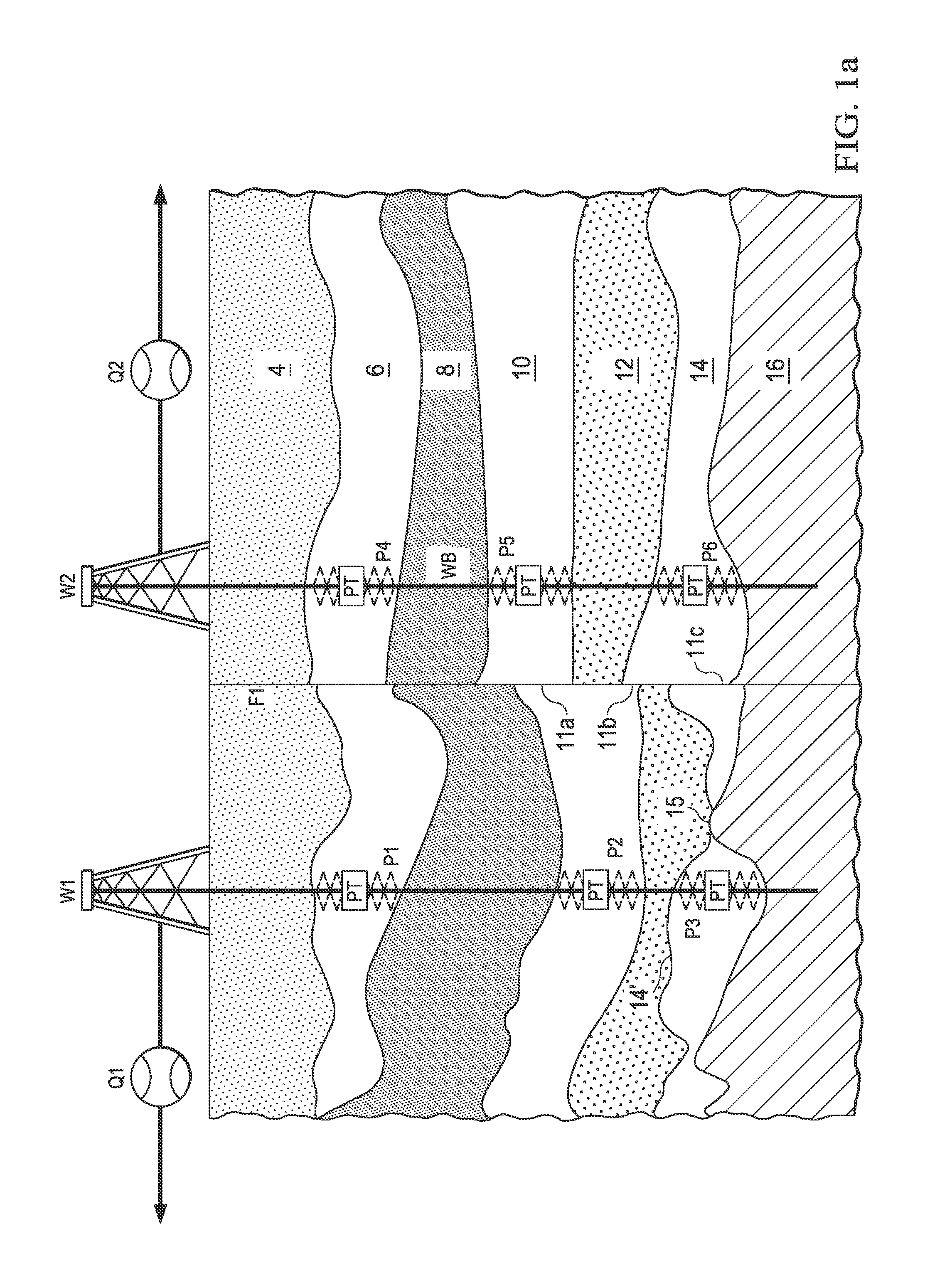
surface structure of many reservoirs presents complexities such as variable
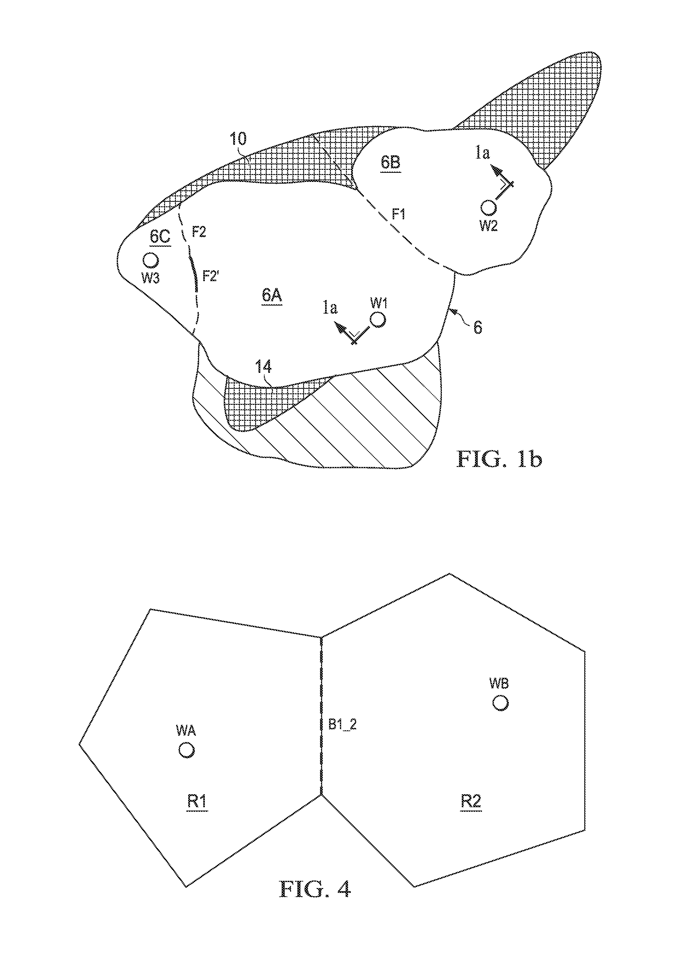
porosity and permeability of the rock, and such as fractures and faults that compartmentalize formations in the reservoir and complicate sub-surface fluid flow.
As known in the art, the ability of conventional exploration technologies of seismic
prospecting,
magnet surveying, and gravitational surveying to accurately portray the structure and contents of sub-surface strata becomes poorer as the depth of interest increases.
As a result, the understanding of the structure and
connectivity of sub-surface features provided by seismic and similar surveys is necessarily imprecise.
However, the information gained from well logs is valid only at the specific location of the well, and provides little
visibility into the reservoir at any significant distance away from the well.
Furthermore, as the depths of interest for newly developed formations increase, so does the cost of drilling and
logging exploratory wells.
For these reasons, well logs provide only limited insight into the sub-
surface structure, architecture, and
connectivity of many newly-developed and producing reservoirs.
Furthermore, reliable downhole pressure sensors are now often plumbed into the
production string and left in the wellbore during production.
While these downhole
pressure measurement data are theoretically valuable in understanding reservoir behavior, the ability of conventional techniques to characterize and evaluate reservoir architecture and
connectivity remains somewhat limited.
Unfortunately, it is difficult to maintain the flow rate of a well precisely constant for an extended period of time.
Furthermore, the
pressure response to changes in flow rate has a very long
time constant, and as such long-ago periods in the flow rate history of a well affect its current downhole pressure.
However, PTA well tests are costly from the standpoint of lost production, and also require significant operator involvement to carry out the shut-in and operation at a constant flow rate, especially given the time period required for such a test (which can extend over several days or weeks).
However, the ability of conventional pressure
transient analysis to provide significant information regarding the detailed structure of the reservoir is limited by the absence of directionality in the pressure measurements.
The time over which data suitable for pressure-rate
deconvolution can be gathered and reasonably deconvolved remains limited to that provided by a conventional
well test, which typically does not run beyond two weeks or so.
In typical production fields, this limited
test duration limits the
radius of investigation to about several thousand feet from the well.
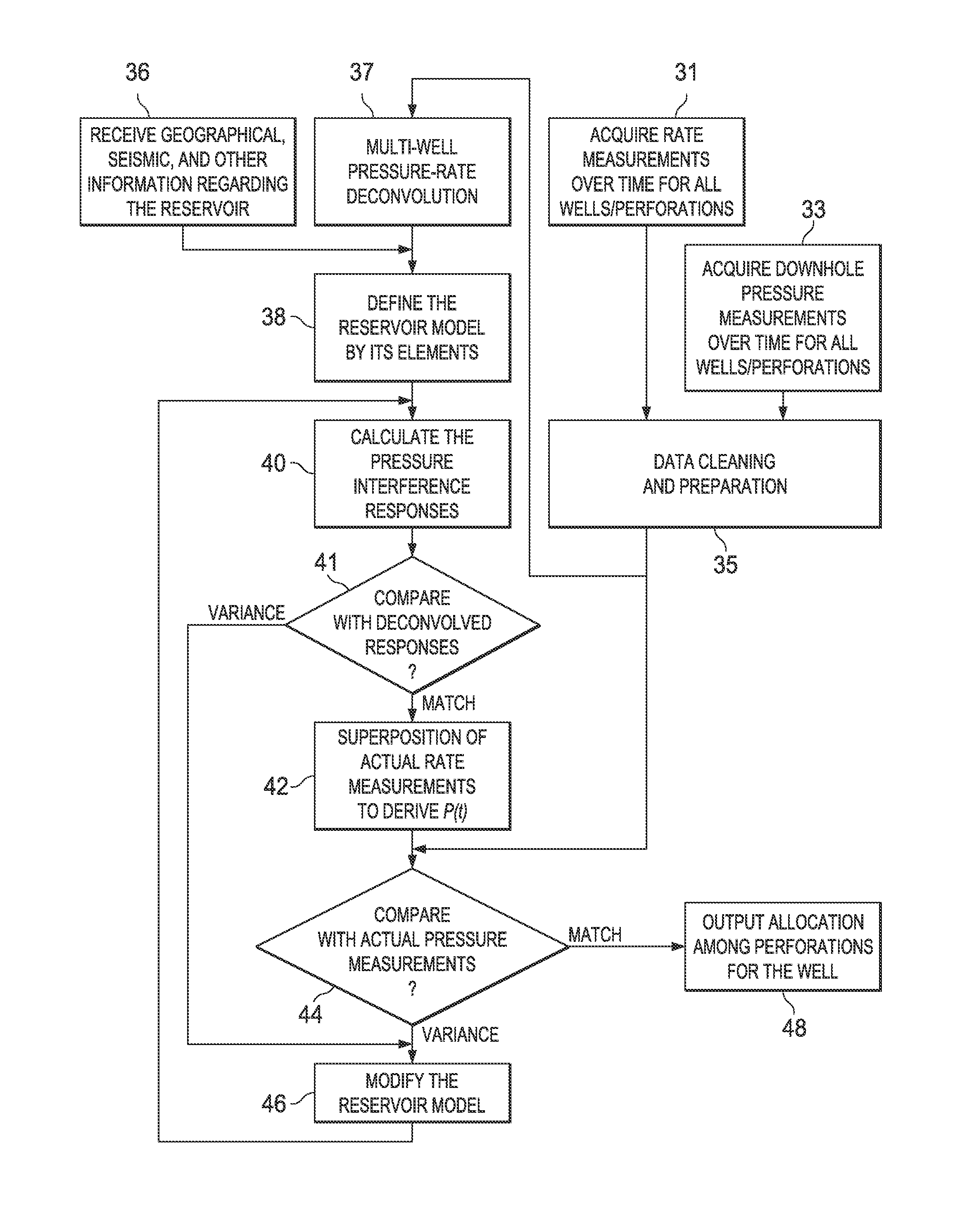
However, in typical production fields, multiple wells are producing from the same formation at the same time, and the flow from each well producing from a given formation not only affects the wellbore pressure for that well, but also affects the wellbore pressure in other wells producing from that same formation and from other formations connected to that well.
These constraints thus dramatically increase the cost of a
well test (and thus reduce the frequency of such testing), and decrease the usefulness of the well test in exploring formation structure and connectivity.
However, conventional pressure
transient analysis is limited in its ability to analyze these not-so-well-behaved pressure and rate data acquired during production.
In addition, the complexity presented by the inter-well effects mentioned above also overwhelms these conventional approaches.
However, serious limitations in these conventional finite-element and finite-difference models and simulator techniques preclude their ability to simulate the pressure transient behavior in the wellbore to an extent that could be directly compared with the actual pressure measurements obtained by downhole gates in the wells.
However, given the limitations described above, it is difficult to correlate reservoir simulations with measurements of flow rate, temperatures, downhole pressure, and the like obtained during production and during shut-in and draw-down events.
On one hand, as described above, the resolution of seismic and other conventional geological surveys is relatively coarse.
Therefore, even if the model were accurate, the simulated
reservoir pressure for a grid element may not match the measured
reservoir pressure at the precise location of the well within the grid volume.
To summarize, conventional
reservoir modeling and data gathering and analysis techniques are limited in several ways.
These conventional approaches are generally limited to the single-well situation, and thus cannot comprehend the real-world situation of multiple wells producing from the same formation.
In addition, the
time duration that can be analyzed using these conventional approaches is necessarily limited, especially considering that inter-well effects on pressure measurements must be avoided.
Accordingly, the
visibility of this analysis at significant distances from the wellbore into the formation is limited.
In addition, only simple reservoir geometries are suitable for analysis by these conventional techniques.
Unfortunately, these complexities are in fact present in many reservoirs, especially in those oil and gas reserves that are currently being developed at extreme depths and at remote locations.
As such, substantial differences between reservoir behavior as predicted by the model and reservoir behavior as observed via downhole pressure measurements and other measurements often result.
Therefore, despite the availability of a large amount of real-time downhole
pressure data from modern-day production fields, good correlation of that data with conventional reservoir models is seldom attained.
Conventional reservoir models and simulators are also not conducive to efficient reconfiguration and modification.
In addition, long computing times are required to execute these conventional numerical simulators, reducing the ability to interactively modify the model to correspond to observed data, even if good correlation between model and measurements were achievable in the first place.

