
Manufacturing method for plasma display panel

a plasma display and manufacturing method technology, applied in cheese manufacture, cold cathode tubes, butter manufacture, etc., can solve the problems of increasing the cost of the driver, reducing the luminous efficiency, and deteriorating so as to prevent the deterioration of the absorbent material due to the heating in the atmosphere, the effect of reducing the absorbent characteristics

Inactive Publication Date: 2011-02-24
PANASONIC CORP
View PDF13 Cites 0 Cited by
  • Summary
  • Abstract
  • Description
  • Claims
  • Application Information

AI Technical Summary

Benefits of technology

[0034]An earnest study of the inventors of the present invention revealed that once heated at a prescribed temperature or higher in the atmosphere, an absorbent material, such as copper ion-exchanged ZSM-5-type zeolite, is deteriorated while still keeping an impurity gas absorbed within itself, whereby its absorption characteristics is decreased. The inventors also found that such deterioration is avoided by heating the absorbent material in a non-oxidizing atmosphere. Meanwhile, it is known that the copper ion-exchanged ZSM-5-type zeolite preferentially absorbs an impurity gas when brought in contact with both Xe and impurity gases.
[0035]With the stated facts taken into consideration, the present invention provides the following manufacturing method for a PDP. In the evacuation step after the sealing step, at least one exhaust tube into which the absorbent material is inserted is disposed on either a front panel or a back panel in such a manner that the exhaust tube is in communication with the inner space (i.e. discharge space) enclosed by the panels. As the absorbent material, copper ion-exchanged ZSM-5-type zeolite, which absorbs O2, water vapor, CO, CO2, a CH (hydrocarbon) gas, and the others, is used.
[0036]Here, by performing at least a heating and evacuating sub-step in the evacuation step in the non-oxidizing atmosphere, the stated problem, namely that the absorption characteristics of the absorbent material is degraded due to the heating in the atmosphere, is prevented.
[0037]Then, when brought in contact with a discharge gas in a discharge gas introducing step, the absorbent material absorbs a certain amount of Xe contained in the discharge gas. As mentioned above, however, the deterioration of the absorbent material due to the heating in the atmosphere is prevented, and therefore the absorbent material is able to emit the absorbed Xe into the discharge space, while also preferentially absorbing an impurity gas in the discharge space so that the impurity gas is removed.
[0038]Next, a description is given of the effects of absorbing and removing an impurity gas that are realized by the absorbent material.
[0039]Since the absorbent material is inserted into the exhaust tube in communication with the discharge space, it is able to absorb and remove the impurity gas that is released from the phosphor layer to the discharge space in the discharge gas introducing step, a tube-off process, an aging process (in the aging step, in particular) which are performed after the sealing step. The absorbent material can also absorb and remove an impurity gas that is to be generated in the discharge gas while the manufactured product is in use. When deposited on a protective layer containing magnesium oxide, the impurity gas might deteriorate the protective layer and degrade the secondary electron emission characteristics of the protective layer, which leads to an increase in the discharge voltage. However, the present invention realizes an effective removal of a variety of impurity gases (O2, water vapor, CO, CO2, and a CH gas) in the discharge space, by utilizing the absorbent material in the exhaust tube.

Problems solved by technology

However, the problem with the small cells is that they tend to increase the discharge voltage, thereby decreasing the luminous efficiency.
Further, due to the increase in the discharge voltage, the luminous efficiency cannot be greatly improved.
The increase in the drive voltage also brings about another problem, namely, an increase in cost of the driver.
Also, the high-definition and ultra-high-definition PDPs have a larger surface area for barrier ribs than conventional PDPs, while they do not have a larger panel space for the protective layer.
The problem of such an impurity gas in the PDPs is that it prevents Xe from being excited, leading to an increase in the discharge voltage.
These effects also result in a decrease in luminous efficiency.

Method used


Image

  • Manufacturing method for plasma display panel
  • Manufacturing method for plasma display panel
  • Manufacturing method for plasma display panel

Examples


embodiment 1

[0051]In Embodiment 1, illustrated is a high-definition PDP 1 with a 42 inch visual size full HD panel of 1920 discharge cells horizontally×1080 discharge cells vertically.

Structure of PDP 1

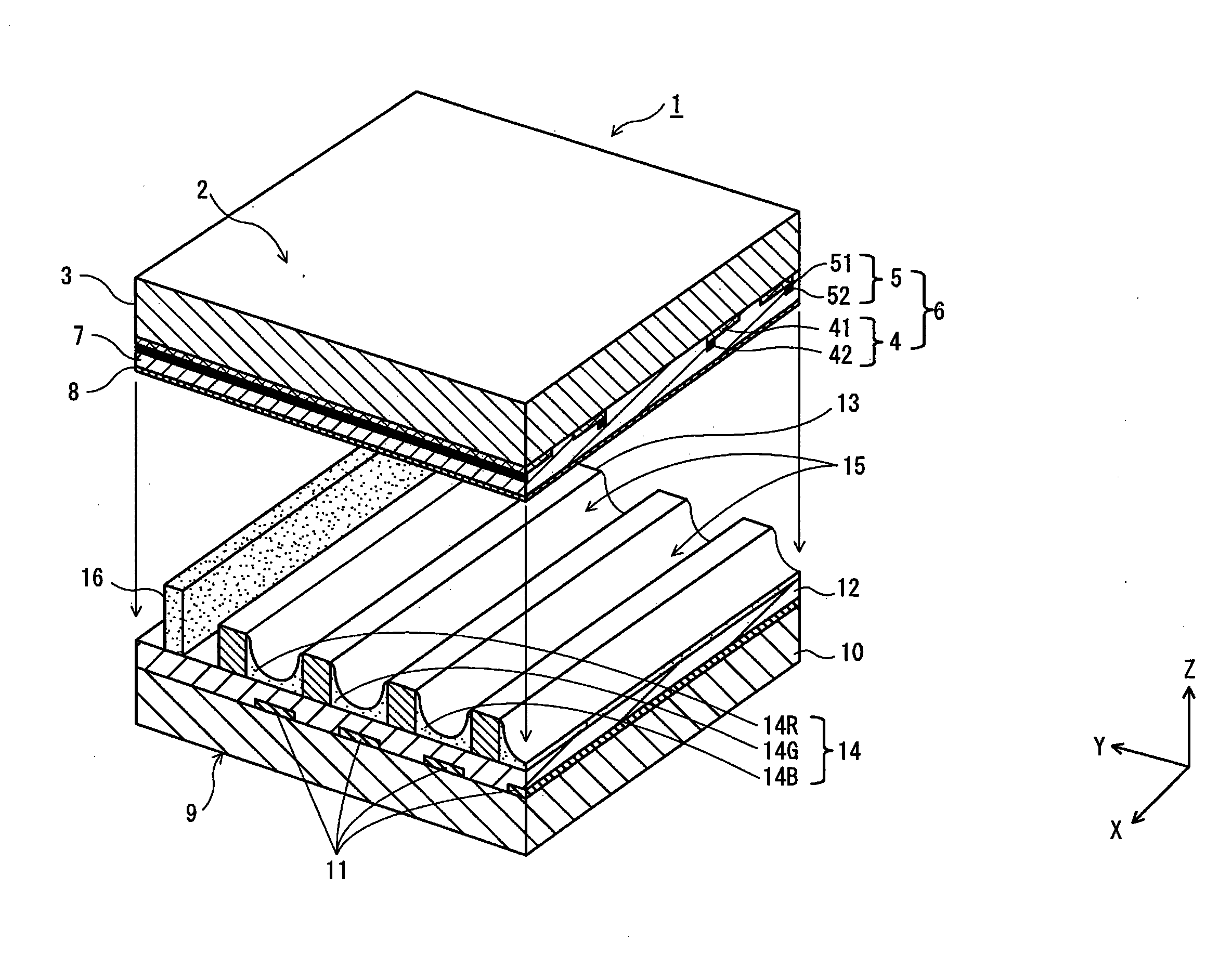
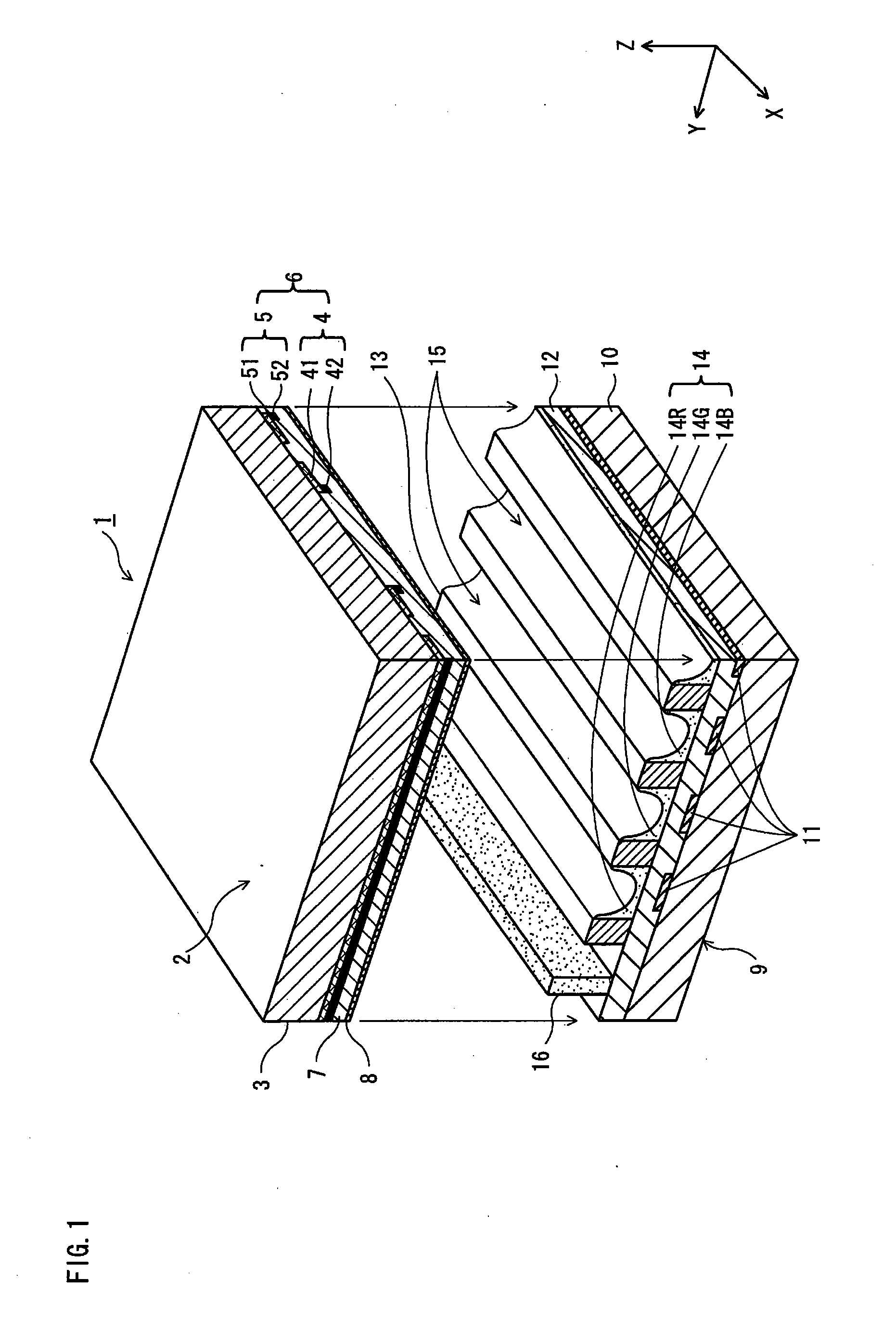
[0052]FIG. 1 is a partial perspective view showing the structure of the AC PDP 1 according to Embodiment 1. The figure partially shows a peripheral portion of the PDP 1 in which a sealing part is located.

[0053]The PDP 1 consists mainly of a front substrate (front panel) 2 and a back substrate (back panel) 9 that are sealed together at the peripheral edges thereof in a manner such that the panels 2 and 9 are superposed with a main inner surface of the front panel 2 opposing a main inner surface of the back panel 9.

[0054]As shown in FIG. 1, the PDP 1 is composed mainly of a first substrate (front substrate 2) and a second substrate (back substrate 9) that oppose each other with a main surface of the first substrate facing a main surface of the second substrate.

[0055]The front substrate 2 includes a...

embodiment 2

[0170]A description is given of the PDP according to Embodiment 2 of the present invention, focusing on differences between Embodiment 1.

[0171]The main feature of the PDP according to Embodiment 2 lies in a point in the manufacturing method that a larger amount of the Xe gas is introduced, by setting the pressure of a discharge gas introduced into the discharge space 15 in the discharge gas introducing step to be higher for a certain degree (i.e. pressurization), in anticipation of an amount of the Xe gas introduced in the discharge space 15 to be absorbed by the absorbent material 39. By this means, the PDP according to Embodiment 2 fully addresses the problem, namely, that the luminance characteristics varies as a result of a Xe gas in the discharge gas composition being absorbed by the absorbent material and thereby varying the composition and pressure of the discharge gas.

[0172]Assume that Xe absorption capacity of the absorbent material 39 is x (cm3 / g), the total volume of the ...

embodiment 3

[0176]The PDP according to Embodiment 3 differs from Embodiment 1 only in a point that the absorbent material 39 which has been caused to absorb a Xe gas in advance is used in the absorbent material inserting sub-step. This reduces the amount of the Xe gas in the discharge space 15 to be absorbed by the absorbent material 39 after the discharge gas is introduced, thereby preventing the variation of the discharge gas composition due to the absorbent material, thus maintaining a stable discharge characteristics of the PDP.

[0177]In the case where copper ion-exchanged ZSM-5-type zeolite is used as the absorbent material 39, it is possible to cause the absorbent material 39 to absorb a Xe gas by exposing the material 39 to Xe gases by heating in a non-oxidizing atmosphere. Upon exposure to the atmosphere, however, the material 39 preferentially absorbs an impurity gas in the atmosphere and emits the Xe gas, as mentioned above. Accordingly, in Embodiment 3, the material 39 is inserted int...


PUM

PropertyMeasurementUnit
Lengthaaaaaaaaaa
Fractionaaaaaaaaaa
Softening pointaaaaaaaaaa

Abstract

The present invention aims to provide a manufacturing method for a PDP which allows even high-definition and ultra-high-definition PDPs to demonstrate an excellent image display capability at improved luminous efficiency, by suppressing variation of a discharge gas composition, and by eliminating an impurity gas in a discharge space effectively.To achieve the aim, deterioration of an absorbent material 39 composed of copper ion-exchanged ZSM-5-type zeolite is prevented, by performing both sealing and evacuation steps for the front substrate 2 and back substrate 9 in a non-oxidizing gas atmosphere. This maintains properties of the absorbent material 39 for absorbing the impurity gas without degradation, even if the absorbent material 39 absorbs a Xe gas in a discharge gas introducing step.

Description

TECHNICAL FIELD[0001]The present invention relates to a manufacturing method for a plasma display panel capable of driving with high efficiency and with low voltage, and in particular to techniques for preventing deterioration of a protective layer and for maintaining the composition of a discharge gas.BACKGROUND ART[0002]Due to the ongoing development in an image quality of PDPs (Plasma Display Panel) that display an image using gas discharge, full HD (High Definition) panels which are capable of displaying hi-vision (high-definition) broadcasts while maintaining the original quality have been becoming popular. The full HD panels have discharge cells having an extremely smaller size than conventional panels. For example, a 42 inch visual size full HD panel has 1920×1080 discharge cells with a cell pitch of approximately 150 μm. A super hi-vision (ultra-high-definition) panel which is now being planned has approximately 8000×4000 discharge cells in the same visual panel size. An ult...

Claims


Application Information

Patent Timeline
IPC IPC(8): B29C65/02B32B37/00H01J17/49
CPCH01J9/385H01J9/39H01J11/52H01J11/12H01J9/395
Inventor SAKAI, MASAHIROOKADA, KEISUKEOKUI, YAYOI
Owner PANASONIC CORP
Learn More